A basic semiconductor diode can operate in forward bias but it cannot conduct during reverse bias. The special type of diode that can conduct in reverse bias is referred to as a Zener diode. This diode can conduct in forward bias just like a normal diode. The junction for the Zener diode will be heavily doped. Because of this reason, it can work as normally as a basic junction in forwarding bias and can tolerate the reverse currents during reverse bias. The main purpose of it is to use in stabilizers.
What is a Zener Diode?
A diode in which the flow of current is from anode to cathode and cathode to anode defining that it has the capacity of conducting in both forward and reverse biases are referred to a Zener diode.
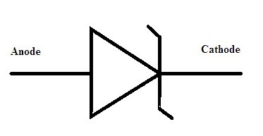
Symbol of Zener Diode
Working Principle:
- Usually, the condition of the diode with basic p-n as its junction during reverse bias is that there is no chance of conduction because the depletion region width is comparatively high.
- As the applied reverse voltage tends to increase that result in the increment of the width of the depletion region. Even there exist some minority carriers which gain some energy because of increment of reverse voltage.
- Due to the gain in kinetic energy of the minority carriers, these free electrons in movement collide with the stationary ions. This results in the formation of more free electrons.
- Further, these again collide with remaining stationary ions and this process continues it is referred to as carrier multiplication.
- Because of carrier multiplication, a huge multiple of free electrons are created and the complete region of the diode becomes conductive resulting in the breakdown known as avalanche breakdown.
- Generally, this is not the case in the Zener diode. In Zener diode, the junction is doped with the highest concentration. Because of this reason when the reverse voltage has applied the width of the depletion region tends to minimize.
- As there exist the maximum concentration of the impure atoms in it. It creates the maximum number of ions in it.
- As soon as the diode exceeds the threshold value the electrons that are in the covalent bonds tend to come out in the depletion region so that it can make depletion region conductive.
- Hence this type of breakdown is referred to as Zener breakdown. The occurrence of this breakdown will be at certain voltage termed as Zener voltage.
- Just as cut in voltage in normal diode here it is Zener voltage. Once the applied voltage exceeds the value of voltage it tends to conduct.
- This value of the Zener voltage is properly adjusted at the time of manufacturing by the proper concentration in doping.
- In case of occurring of break down further, there is no possibility of occurrence of avalanche breakdown.
This is the principle lying behind the functioning of the diode.
Please refer to this link to know more about Zener Diode MCQs
Zener Diode Circuit
The circuit for this type of diode is very simple. One has to connect the highly doped junction in reverse bias. The circuit can be represented as follows.
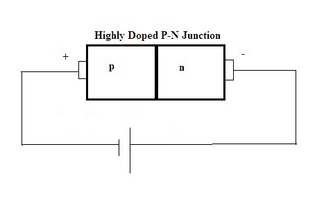
Zener Diode Circuit
Characteristics
The graphical representation can give basic characteristics. These are normally termed as V-I characteristics.
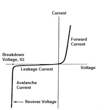
Zener Diode V-I Characteristics Curve
As per the above analysis, it is evident that during forwarding bias Zener diode characteristics will remain the same as that of the normal diode. Whereas after the applied voltage crosses the value of Zener voltage (Vz ) the Zener breakdown takes place. After the breakdown, the flow of the current in the circuit tends to increase immediately.
Experiment
The main aim of this experiment lies in to find out the basic value of the Zener voltage. Once the values are found it should be plotted as characteristics curve. Zener voltage is the basic voltage that is set as the cut-off value, and the breakdown value of the voltage must be lying close to the desired value that we want it is just approximated.
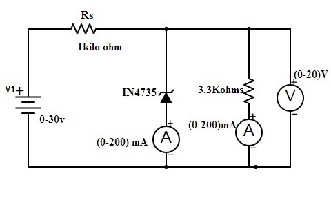
Zener Diode Experiment
The list of the components of equipment required to perform this experiment mainly include Zener diode, Milliammeter, Voltmeter, and DC supply(variable), and Resistors
- Firstly the connections are made as per the circuit diagram.
- To the circuit, the reverse voltage applied varies slowly.
- Then simultaneously note down the voltmeter and ammeter readings.
- There are two ammeters present in the circuit. One is connected in series to the diode whereas other is connected in series to the resistor.
- As the minimum voltage applied to the circuit exceeds one can observe sudden spikes in ammeter connected to the diode. At this time note down the readings for both ammeters and voltmeter.
- Even further application of voltage values can see that current values increase in the circuit but the voltage remains constant across the diode.
- This has been done by connecting the diode in reverse bias voltage and current readings are tabulated. Similarly, experiment by keeping the diode in forwarding bias and tabulate the readings.
- Once the values are noted the plot of characteristics curves between voltage and current is plotted.
- From the plot at which point of voltage the spike in current is noticed that voltage value is referred to as Zener breakdown voltage.
- Based on the requirement of the voltage for the particular device the diode with that particular breakdown voltage has been chosen.
- Hence in this way, the experiment is performed so that the breakdown voltage value can be found.
Applications
The applications for this diode are illustrated below.
- As it has the property of maintaining the low voltages even though high voltages are applied. These are preferably applicable in voltage regulators.
- It is preferably used in ammeters, voltmeters, and ohmmeters because here the reference voltage is required.
Zener Diode as Shunt Regulator
As the principle of the Zener diode is already discussed. When the reverse voltage applied to it crosses the basic Zener voltage the diode starts conducting.
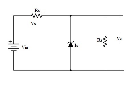
Shunt Regulator
Once the voltage limit has been crossed there is no increment in the voltage after it but in the current, we can see the increment.
The range of breakdown/zener voltage lies is from 12v to 1200 v based on its typical application.
The voltage that is to be regulated is across the resistor Rz. To it, a diode is connected. Whatever the voltage has been selected to be regulated it must not cross the limit value that is Vz. Based on it a diode with certain breakdown voltage has been selected so that it satisfies the above criteria.
Zener diode is connected in reverse bias, so once the Zener voltage exceeds then the current flows through the diode but there is an unnoticeable voltage drop. Hence in this way the voltage is limited across the load. In this way, it is used as a voltage regulator. This is considered as the basic application of Zener diode.
Power Dissipation of Zener
As the points discussed till now make it very clear that Zener diode will be conducting in reverse bias. Generally, the power dissipated is the multiplication of overall current and voltage values.
In Zener diode, it is determined as
P = VZ X IR
Where VZ stands for Zener voltage and IR represents the reverse current.
Please refer to this link for Choosing resistor values for diodes.
Differences between Diode and Zener Diode
|
Diode |
Zener Diode |
|
(1) The basic diode with p-n as its junction its conduction will be limited in forwarding bias. |
(1) Here the conduction is evident in both forward and reverses biases. |
|
(2) The level of doping is low in this type of diode. |
(2) The level of doping here is high. |
|
(3) As the reverse current flows here the diode junction gets damaged. |
(3)As it is conductible in reverse bias the reverse current will not affect the junction of it. |
|
(4) This obeys Ohms law. |
(4)It doesn’t prefer Ohms law |
|
(5) It is basically used during the rectification. |
(5) It can be applicable for controlling voltages as shunt regulators etc., |
The above comparison between both types gives us a basic knowledge of it. It is very much clear that diode with basic or lightly doped junction has the only capability of carrying the forward current but this diode has the strength of handling both forward and reverse currents because of its highly doped junction.
Then can you answer a simple question can we utilize Zener diode for rectification as well as for regulation at a time in a single circuit?