In radio and optical communications, a transceiver is a combination of transmitter & receiver within a single package. The main function of this module is to transmit & receive radio signals for communication purposes with an antenna. So these two functions are combined frequently within a single device to decrease manufacturing costs. In LANs, the transceiver module is an element of the NIC (network interface card). It is also used in wireless communication devices like mobile phones, cordless telephones, etc. In cell phones, this module can send & receive the phone conversation two sides by radio waves to a cell tower whereas, in cordless phones, the transceivers are used at both the handset of the phone & the base station to communicate. This article discusses an overview of the 2.4Ghz XY-WA transceiver module, working, interfacing, and its applications.
What is XY-WA Transceiver Module?
XY – WA 2.4Ghz transceiver module is a type of RF module used to transmit up to 100mWatts power by up to 1 Mbps high transmission rate at a 250m transmission range using the transmission. These RF modules are extensively used for wireless communication to communicate above long distances through a high data rate transmission with a license-free open ISM band. This module is used for mounting on custom circuit boards to decrease the size & design a compact device.
The XY-WA transceiver module is available in two types type-a & type-b. Type-A is the soldering or PCB welding type used in compact applications whereas Type-B is the pin-type module which is very convenient to use directly by soldering 2.54 pitch connectors.
Pin Configuration:
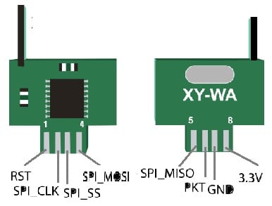
The pin configuration of the XY-WA transceiver module is shown below. This module includes 8 pins where each pin and its function are discussed below.

XY-WA Transceiver Module Pin Configuration
Pin1 (RST): It is a reset pin, used to RESET the module.
Pin2 (SPI_SCK): It is a serial clock pin, used to accept the CLK signal through master.
Pin3 (SPI_SS): It is a slave select pin, used for selecting which slave device is used to exchange data.
Pin4 (SPI_MOSI): It is a master-out slave-in pin used to transmit the data toward peripherals.
Pin5 (SPI_MISO): It is a master-in slave-out pin used to transmit data to the master.
Pin6 (PKT): It is a packet pin used to transmit the packets on the channel.
Pin7 (GND): It is the ground pin of the module.
Pin8 (3.3V): It is a power pin that transmits power toward the module.
Features & Specifications
The features and specifications of the XY-WA transceiver module are discussed below.
- It is a Type A XY-WA model.
- The type of interface used is SPI.
- Data rate is 250Kbit/s, 1Mbit/s, 62.5Kbit/s & 125Kbit/s.
- It has an in-built silicon antenna.
- Its operating frequency ranges from 2.400 to 2.525GHz
- Its LXWXH is 12x9x2 mm.
- Its weight is 3 gm.
- SPI interface helps the communication through MCU I/O port.
- Its transmission power is up to 100mW.
- Its maximum transmission data rate is up to 1Mbps.
- Its transmission range is up to 250 meters.
- It utilizes an SPI interface for communicating between master & slave devices.
- It uses a global 2.4GHz license-free open ISM band.
- Its operating voltage ranges from 2.2 to 3.6 V.
- Its operating temperature ranges from -40 to 85 degrees Centigrade.
- Its emission current ranges from 15 to 24 mAmps.
- Its reception current is 18mAmps.
- Its sleep current is 6uAmps.
- Alternative XY-WA modules are; 433MhZ RF Module, HC12, LoRa & nRF905.
Working
XY-WA transceiver module works by using a 2.4 GHz ISM band range for communicating between two devices. It is very significant for both nodes to be on a similar frequency band to commune between two nodes with radio frequencies,. The frequency range of the XY-WA module ranges between 2.4 GHz – 2.5 GHz.
The XY-WA transceiver module can be connected to a zero board with the help of some male jumper wires to make it suitable for connecting it to any microcontroller. The bandwidth occupied on each channel of the two modules is below 1Mhz. By considering the above range of frequency, we can obtain 125 channels. To determine the selected channel’s frequency, the formula used is Frequency (f) = 2400 + Selected channel. If the possible channels are 125, then you can utilize from 0 – 125 value & put it within the selected value of the channel & decide the channel frequency that will be utilized.
XY-WA Transceiver Module Interfacing with Arduino Uno
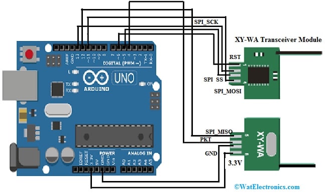
XY-WA transceiver module interfacing with Arduino Uno is shown below. The required components for this interfacing mainly include XY – WA 2.4Ghz transceiver module, Arduino Uno, and jumper wires.

XY-WA Transceiver Module Interfacing with Arduino Uno
The connections of this interfacing follow as;
- The pin1 like the reset pin of the XY-WA transceiver module is simply connected to the 6th digital pin of the Arduino Uno microcontroller.
- The pin3 like the CS pin of the transceiver module is connected to the 5th digital pin of the Arduino Uno.
- The pin6 like the Packet/Pkt pin of the wireless module is connected to the 4th digital pin of the Arduino Uno.
The SPI interface terminals are connected as;
- The MISO pin of the module is connected to the Arduino board’s 12th pin.
- The MOSI pin of the module is connected to the Arduino board’s 11th pin.
- The clock or CLK pin of the module is connected to the Arduino board’s 13th pin.
- The pin7 like GND & pin8 like 3.3V power pins are connected to the Arduino Uno board’s 7th & 8th pins correspondingly.
The following XY-WA libraries need to be downloaded to use with Arduino from Github.
LT8920.h library is mainly used for low-cost LT8910 or LT8920 2.4Ghz transceiver modules.
SPI.h library is mainly used for communicating between Arduino Uno & the wireless module.
Code
The code below is used for both the communication modules since they are transceivers so that anybody can operate as a transmitter & another one as a receiver & vice versa.
In the following code, the primary step is to include the module libraries. SPI.h is utilized to communicate between the LT8920.h & microcontroller for the module. In addition, describe the RST, CS & PKT.
#include “SPI.h”
#include “LT8920.h”
const unit8_t PIN_NRF_RST = 6; // Arduino Uno Pin = 6
constant uint8_t PIN_NRF_CS = 5; //Arduino Uno Pin = 5
constant uint8_t PIN_NRF_PKT = 4; //Arduino Uno Pin = 4
// Similarly connect MISO = 12
// MOSI = 11 // SCK = 13
char sbuf[32];
LT8920 lt(PIN_NRF_CS, PIN_NRF_PKT, PIN_NRF_RST);
uint8_t a = 0; //+1 with every packet received.
uint8_t b = 105; //Change from 0 to 255 in the receiver and put other numbers
uint8_t c = 218; //Check signal
uint8_t d = 53; //reception / transmission
uint8_t e = 95;
void setup()
{
Serial.begin(9600);
SPI.begin();
SPI.beginTransaction(SPISettings(12000000, MSBFIRST, SPI_MODE1));
SPI.setClockDivider(SPI_CLOCK_DIV16);
lt.begin();
lt.writeRegister(35, 0x0F00); //Setting the number of repeated dispatches to 255
lt.setCurrentControl(255,255); //Setting the power and gain
lt.setDataRate(LT8920::LT8920_1MBPS);
lt.setChannel(80); // Setting the Channel
lt.setSyncWord(0x123A123B123C123D); //The receiver and transmitter must be on the same channel
}
void loop()
{
uint8_t data[] = { a,b,c,d,e };
lt.sendPacket(data,5); //Sending the second digit in the number of words in the packet
Serial.print(“Packet send:”); // Printing “Packet send”
Serial.println(a);
a=a+1;
if (a>=256)
{
a=0;
}
lt.startListening(); //We switch to the reception part
delay(1000);
if (lt.available())
{
uint8_t buf[32];
int packetSize = lt.read(buf, 32);
if (packetSize > 0)
{
Serial.println(F(“Packet read OK”)); // If packet received print “Packet read OK”
for(int i = 0; i < packetSize; i++)
{
Serial.print(i);
Serial.print(“=”);
Serial.println(buf[i]);
}
}
}
else
{
Serial.println(F(“Packet read –“));
}
}
In the above interfacing, both the RF modules are connected to the Arduino board and then connected to the laptop. Once the code was uploaded to both the RF modules & the serial monitor was monitored. According to the described print commands within the above code, we can monitor that the packets are being transmitted & received through the RF modules.
How to Increase the XY – WA RF Module Range?
There are many ways to increase the XY – WA RF module RF range which are discussed below.
- By increasing the power of the transmitter module, most RF modules can be arranged to transmit a custom o/p power & a high transmission power can be utilized for increasing the range.
- By decreasing the transmission data speed, a lower data speed above a channel covers longer ranges.
- Altering the frequency channels also serves as a great option because low-frequency bands are obtained through the Wi-Fi (or) other signals. Changing to a high-frequency band can eliminate any type of interference by increasing the range.
Problems
The problems faced while choosing RF modules are discussed below.
- An improper power supply can induce noises & lead to improper functioning of the module.
- At the transmitting & receiving ends, an extremely low voltage supply can also turn into a problem. So selecting an adapter is best because it provides a stable o/p voltage supply.
- Because of the low-quality antenna.
XY-WA Transceiver Module Applications
The applications of the XY-WA transceiver module include the following.
- XY-WA wireless transceiver module is used to transmit data above long distances (maximum 250 meters) on the 2.4GHz frequency & with 1Mbps highest transmission speed.
- This transceiver module is used in mesh Networking.
- It is used in several wireless control applications.
- This module is used in RF remote controllers.
- These are used in Antijamming models, aircraft & Toys.
Thus, this is an overview of XY-WA 2.4G wireless transceiver module which transmits data above long distances on the 2.4GHz frequency with 1Mbps transmission speed. The FIFO operation mode ensures a smooth flow of data between the module and the MCU system. The antenna incorporated through the PCB allows up to 100 power transmissions. This transceiver module is compatible with different microprocessors like ARM/ MCU/MCU/ STM32/AVR/ PIC & Arduino development kits. It is extensively used in security installations, industrial, telemetry, aero modeling, etc. Here is a question for you, what is an antenna?