XBee module is a wireless connectivity module designed by Digi International. In the year 2005, the first ‘XBee module’ was launched under the brand of MaxStream. This module is based on the standard of IEEE 802.15.4-2003 mainly used for star & point-to-point communications. The family of XBee has developed and a complete ecosystem of wireless modules, adapters, gateways & software. These modules are generally available in three form factors. Except for XBee 868LP, all XBees are available in 20-pin TH (through-hole) form-factor whereas the current XBee modules are available in MMT (micro-mount) & SMT (surface-mount) form-factors. These are most popular to use in high-volume applications because of the low manufacturing SMT costs. This article provides brief information on the Xbee S2C module, pin configuration, specifications, and applications.
What is the Xbee S2C module?
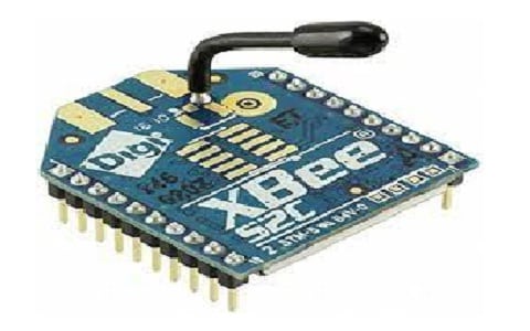
The XBee S2C is a different type of RF module that provides various communication techniques, that cover almost every microcontroller with it. The XBee S2C communication module transmits the data at 2.4GHz speed. This module’s communication technique is to create a network and communicate through each other for the transmission of data.
This module is mainly used because of its simple usage technique with every equivalent module-based network. This module is well-suited by other units that utilize ZigBee technology like other ConnectPortS gateways, XBee modules, XBee Sensors, XBee-PRO Adapters, etc. To configure the XBee module in any operating mode, Digi International provides an X-CTU software tool. This tool is helpful in configuring the device, testing the performance of the device & upgrading firmware.

Xbee-S2C-Module
Pin Configuration:
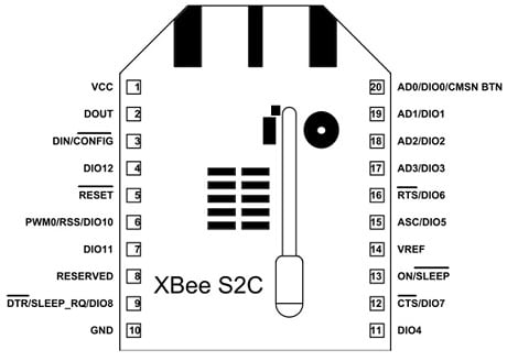
The pin configuration of the Xbee-S2C module includes the following.

Pin Configuration
Pin1 (VCC): This pin is used to provide input power to the device.
Pin2 (DOUT/DIO13): This pin works as a UART serial output and also acts as a GPIO pin.
Pin3 (DIN/CONFIG/DIO14): It acts as a serial data i/p of UART and as a GPIO pin
Pin4 (DIO12/SPI_MISO): This is the data o/p pin for SPI communication and is also useable for GPIO functions.
Pin5 (RESET): This RST pin helps in resetting the device through an external signal.
Pin6 (RSS/PWM0/DIO10): This pin is used for GPIO & PWM pins but simultaneously it is also used for indication of signal strength within UART serial communication.
Pin7 (PWM1/DIO11): This pin works as GPIO & PWM.
Pin8 (RESERVED): It is a no connection or do not connect pin.
Pin9 (DTR/SLEEP_RQ/DIO8): This pin is very helpful in controlling the XBee S2C module’s sleep line & also works as a GPIO function.
Pin10 (GND): This is a GND pin.
Pin11 (DIO4/SPI_MOSI): This pin works as a GPIO pin although it assists in SPI communication for XBee’s data input.
Pin12 (CTS/DIO7): This pin acts as an indicator of RS232 communication to clear the flow control and is also helpful for GPIO functions
Pin13 (ON_SLEEP/DIO9): This pin helps in checking the XBee status and is also functional for GPIO functions.
Pin14 (VREF): This pin is helpful for direct ADC interface within analog voltage reference.
Pin15 (ASC/DIO5): This pin helps in acquiring the signs of a sleep mode device & diagnostic mode. This pin also works for GPIO pins.
Pin16 (RTS/DIO6): This pin is used to indicate the current flow within RS232 communication. This pin can also work as a GPIO pins.
Pin17 (AD3/DIO3/SPI_SSEL): This is a slave select pin for SPI communication and it also works as an Analog data input & GPIO pin.
PIn18 (AD2/DIO2/SPI_CLK): This is a CLK pin of the SPI communication and this pin can also work in Analog i/p & GPIO as well.
Pin19 (AD1/DIO1/SPI_ATTN): SPI_ATTN pin assists in getting the notice of the master when there is a data o/p from the XBee module and this pin can also work as GPIO & Analog i/p.
Pin20 (AD0/DIO0/CMSN BTN): This pin is used for the Commissioning button and also used for GPIO & ADC i/p.
Features & Specifications:
The features and specifications of the Xbee-S2C-Module include the following.
- Xbee-S2C-Module is a stand-alone device.
- Xbee-S2C-Module’s transmission frequency ranges from2.4GHz to 2.5GHz
- It includes 16 direct sequence channels.
- It has two interfaces; UART with a maximum of 250 Kb/s & SPI with a maximum of 5 Mb/s.
- Its transmitting power can be adjusted by software.
- The range of urban or indoor is 200 feet.
- The range of RF line-of-sight outdoors is up to 4000 feet.
- Transmit power o/p in boost mode is 6.3mW or 8dBm) and in normal mode is 2mW or 3dBm.
- RF data rate is 250,000 bps.
- The sensitivity of the receiver is -102dBm within Boost mode and -100dBm within normal mode.
- The range of supply voltage ranges from +2.1 to +3.6 volts.
- Its operating current is 33mA at 3.3Volts for normal mode and 45mA at 3.3Volts for boost mode.
- Its idle current is 9mAmps.
- Max o/p current is 40mAmps
- Its power-down current is <1uA.
- ESD protection is 3000V.
- Its operating temperature ranges from -40ºC – 85° Centigrade.
- The data transmitted by microcontroller at UART communication is up to 256kbs however the data transmission rate can expand up to 5Mbs through SPI communication.
- This module’s data rate is up to 250,000bps.
Operating Modes
Xbee-S2C-Module operates in two modes; AT command mode and API mode which are discussed below.
In AT command mode or transparent mode, the available data on the DIN pin can be transmitted directly to the receiver. The API mode is different as compared to the AT command because the data is first changed into the frame & then transmitted. The frame includes multiple sets like start delimiter, type, frame length, data, and checksum to make communication much safer. In this mode, the setting of parameters & feedback of packet delivery can be checked.
How to use XBee S2C Module?
This module can be used very easily & it is always in the network shape. A single XBee works on three kinds of functions which are discussed below.
Coordinator/Manager
An XBee network operates by using a coordinator that works on allocating & managing functions protocols within the network. It is in charge of the node’s synchronization in between the network. The Coordinator will assign each channel & PAN ID to form the network. In every network, there is a single Coordinator that creates the network. The coordinator’s main function is to act like a bridge from one end to the other end to transmit the data. The coordinator allows routers and end devices to join the network and assist in routing data.
Router
The second network part is a router, so there is a router within each type of network. The main function of the router is to deliver the data between two networks by creating a bridge between them. So it establishes the path in between node to node inside & outside the network.
End Device
The end device cannot begin route or network data. The main function of this device is to transmit or receive RF data throughout its parent node like router or coordinator. This device goes into low power mode to save power due to limited functionality.
PAN ID
Personal area network ID is uniquely used to define each network and is very common in all similar network devices. PAN ID is configured in Xbee devices to connect network or to choose a near PAN ID to connect to their network. The coordinator should choose a PAN ID & channel to begin a network. The Coordinator & router allow other devices to connect the networks based on the PAN ID.
Channel
Xbee modules support 16 channels and each channel can be used through a single END DEVICE. The coordinator decides between the channel & PAN ID which to use. The number of channels differs between one XBee to another XBee because some modules have two whereas XBee S2C has a maximum 16 numbers of channels.
Xbee S2C Module Interfacing with Arduino & NodeMCU
The interfacing of the XBee S2C module with Arduino Uno board and NodeMCU is shown below. This interfacing mainly includes transmitter and receiver sections where in the transmitter section, Xbee-S2C-Module is interfaced with Arduino, and in the receiver section, Xbee-S2C-Module is interfaced with NodeMCU. The required components to make this interfacing mainly include; an Arduino Nano board, NodeMCU, XBee Pro S2C module-2, push button, XBee explorer board for programming XBee module, and LED.
Xbee-S2C-Module Interfacing with Arduino Nano at Transmitter Side
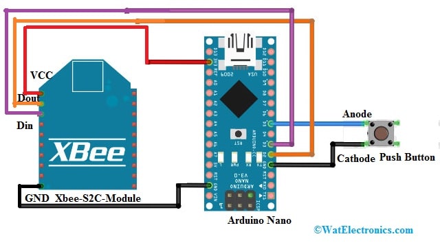
The Xbee-S2C-Module Interfacing with Arduino Nano at the Transmitter Side is shown below. We can also use NodeMCU or Arduino Uno boards The connections of this interfacing follow as;

Xbee-S2C-Module Interfacing with Arduino Nano
- Connect pin 1(VCC) of the XBee S2C module to the Arduino Nano board’s 3.3V pin.
- Connect pin 10 (GND) of XBee to Arduino Nano board’s GND pin. So these two connections will power the transmitter section of the XBee module.
- Connect pin 2 (Dout) of Xbee to Arduino Nano’s D2 pin.
- Connect pin 3 (Din) of Xbee to Arduino Nano’s D3 pin.
- Connect the push button on one end to Arduino Nano’s D5 pin & the other end is connected to the GND terminal. In the above interfacing, a push-button is used. Once this button is pressed, it will send data.
Xbee-S2C-Module Interfacing with NodeMCU at Receiver Side
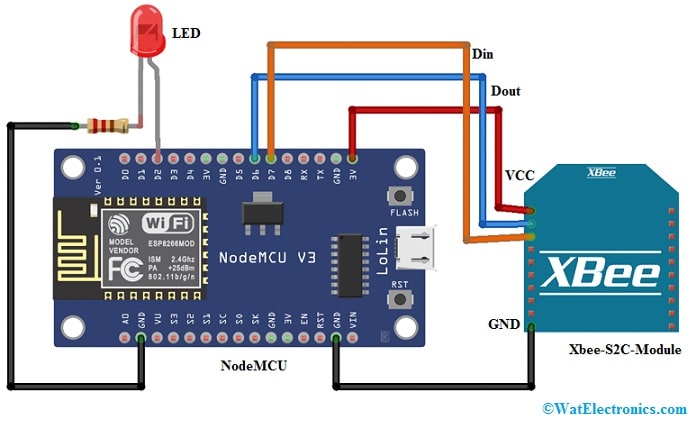
The Xbee-S2C-Module Interfacing with NodeMCU at the receiver side is shown below. We can also use Arduino Uno or Nano boards. Here we use NodeMCU to show the XBee module’s compatibility with different types of microcontrollers. In addition, NodeMCU can also be used for transmitting data to the internet if we transmit sensor data. The connections of this interfacing follow as;

Xbee-S2C-Module Interfacing with NodeMCU
- Connect pin10 (Gnd) of the XBee module to the GND pin of NodeMCU.
- Connect Pin1 (Vcc) of XBee module to 3.3Volts pin of NodeMCU. These two connections are helpful in providing a power supply to the XBee module.
- Connect pin 2 (Dout) of the XBee module to NodeMCU’s D6 pin.
- Connect pin3 (Din) of the XBee module to NodeMCU’s D7 pin for data receiving.
- Connect the anode terminal of the LED to the D2 pin of NodeMCU & cathode pin of the LED to GND using a 220ohm resistor. Here LED is used mainly to indicate whether the data from transmitter to receiver is received or not.
Generally, the XBee module can be arranged as a Coordinator, End device, or Router. To arrange & test your XBee module, XCTU software is necessary which can be downloaded from Google. This software is free, very simple to use, and a multi-platform application mainly for RF XBee modules. Once this software is downloaded and installed, open the application & connect the XBee module with a USB to an explorer board (or) serial converter.
Code
The required code for the transmitter is shown below.
#include “SoftwareSerial.h”
SoftwareSerial XBee(2,3);
int BUTTON = 5;
boolean toggle = false; //this variable keeps track of alternative clicks of the button
void setup()
{
Serial.begin(9600);<br>
pinMode(BUTTON, INPUT_PULLUP);<br>
XBee.begin(9600);
}
void loop()
{
//When button is pressed (GPIO pulled low) send 1
if (digitalRead(BUTTON) == LOW && toggle)
{
Serial.println(“Turn on LED”);
toggle = false;
XBee.write(‘1’);
delay(1000);
}
//When the button is pressed a second time (GPIO pulled low) send 0
else if (digitalRead(BUTTON) == LOW && !toggle)
{
Serial.println(“Turn off LED”);
toggle = true;
XBee.write(‘0’);
The required code for the receiver is shown below.
#include<SoftwareSerial.h>
int led = 2;
int received = 0;
int i;
//For communicating with ZigBee
SoftwareSerial zigbee(13,12);
void setup()
{
Serial.begin(9600);
zigbee.begin(9600);
pinMode(led, OUTPUT);
}
void loop()
{
//check if the data is received
if (zigbee.available() > 0)
{
received = zigbee.read();
//if the data is 0, turn off the LED
if (received == ‘0’)
{
Serial.println(“Turning off LED”);
digitalWrite(led, LOW);
}
//if the data is 1, turn on the LED
else if (received == ‘1’)
{
Serial.println(“Turning on LED”);
digitalWrite(led, HIGH);
}
}
In the above interfacing, two XBee modules are used for establishing ZigBee communication. To communicate between both the XBee modules, an Arduino Nano at the transmitter & NodeMCU at the receiver are used. The XBee modules are coded, so once a push-button is pushed on the Transmitter section, the data is transmitted from transmitter to receiver. Once the receiver receives the data the LED will lit. This signifies that the data transmitted from the transmitter is received accurately at the receiver.
Xbee S2C Module Applications
The applications of the Xbee S2C Module include the following.
- Xbee-S2C-Modules are used in home automation to create a mesh network for safety.
- This module is used in every medium-range communication.
- As compared to other modules, this module is a better choice.
- These are used in the automation of commercial buildings, application control of industries, smart energy, etc.
- The XBee S2C module allows data exchange & communication through ZigBee mesh protocols.
- This module is used where low latency & predictable communication timing is necessary.
- XBee S2C RF module provides cost-effective and very secure network-based wireless communication to electronic devices.
Please refer to this link for the Xbee S2C Module datasheet.
Thus, this is an overview of the Xbee-S2C module. The XBee module supports various wireless communication protocols such as 802.15.4, ZigBee, 868 MHz modules, and many more. Zigbee is a normal protocol used for establishing wireless networking. XBee module is a registered brand of Digi International whereas Zigbee is a registered brand of the Zigbee Alliance. Here is a question for you, what is NodeMCU?