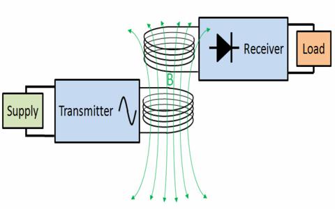
Wireless Power Transfer System
One of the major problems in power system is the losses occurring during the transmission of electrical power. The loss of percentage during the transmission is approximated as 26%. The main cause for power loss during transmission is the resistance of wires used in the grid. According to WRI (world resource institute), the electricity grid of India has the highest percentage (27-40%) of power transmission losses in the world. For this reason, Telsa has proposed methods of electricity transmission using an electromagnetic induction method.
The Serbian scientist “Nikola Telsa” was the first one to research and propose the concept of wireless power transfer in the year 1899, since then many scientists have been working to make his vision a reality. In the same year he has continued research on wireless power transmission in Colorado Springs and writes, the inferiority of the induction method would come into view immense as compared with the distributed charge of ground and air method. In the year 1961, William C. Brown publishes an article exploring possibilities of microwave power transmission. In the year 2009, Sony shows a wireless electrodynamics induction powered TV set.
What is Wireless Power Transfer?
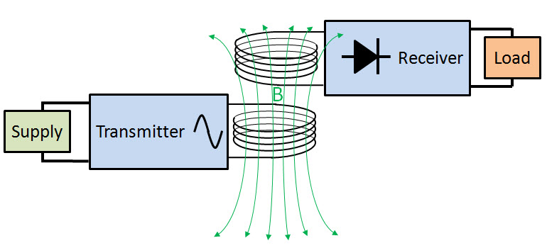
Wireless Power Transfer
Wireless power can be defined as the transmission of electrical energy from a power source to an electrical load without connecting wires. It is reliable, efficient, fast, low maintenance cost, and it can be used for short range or long range. The basic working principle of wireless power transfer is, two objects having similar resonant frequency and in magnetic resonance at powerfully coupled rule tends to exchange the energy, while dissipating relatively little energy to the extraneous off-resonant objects.
Moreover, this method can be involved in a variety of applications, like to charge mobile phones, laptops wirelessly. And also this kind of charging gives a far lower risk of electrical shock as it would be galvanically isolated. This is an emerging technology, and further, the distance of power transfer can be improved as the study across the world is still going on.
Hardware Requirements of Wireless Power Transfer
The hardware requirements of wireless power transfer include HF-Transformer, HF-diodes, rectifier, basic Transistors, Two air filled inductor coils, Voltage regulator and BLDC fan.
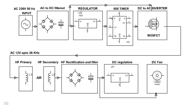
Wireless Power Transfer Block Diagram
HF-Transformer
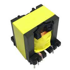
HF-Transformer
High frequency (HF) transformers transfer electric power and the physical size are reliant on the power to be transformed as well as the operating frequency. The emf equation of universal transformer indicates that at a higher frequency, the core flux density will be lower for a given voltage. This implies that a core can have a smaller cross-sectional area.
Voltage Regulator
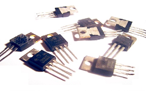
A voltage regulator is an electrical regulator, designed to maintain a constant level voltage automatically.
Voltage Regulator
- There are three terminals positive voltage regulators are available in many packages and also with several o/p voltages, making them useful in a wide range of applications. Output current up to 1A and o/p voltage is 12.
- Thermal overload and short circuit protection
- Output transistor safe operating area protection
Coil
Coil
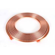
- An electromagnetic coil is formed when a conductor is wound around a core
- Primarily used to transfer energy from one electrical circuit to another by magnetic coupling
- Common types of electrical coils are Tesla, Barker, Choke, Maxwell coil, etc.
IN4007 Diode

1N4148 Diode
- This diode is used as full wave bridge rectifier circuit in this project
- Maximum reverse bias voltage capacity of 50V and max forward current capacity of 1Amp.
Project Working
The main concept of this project is to design a device for the concept of wireless power transfer to eliminate the use conventional copper cables and also current carrying wires.
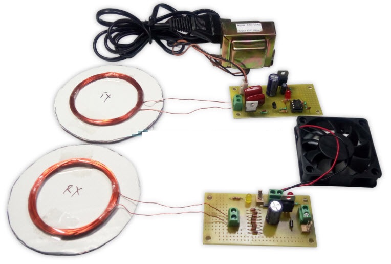
This project is built upon using a circuit which converts AC 230V 50Hz to AC 12V, High frequency (HF). The output is fed to a tuned coil shaping as main of an air core transformer. The minor coil develops a voltage of HF 12volt.
Wireless Power Transfer Project
Thus the power transfer can be done by the primary to the secondary that is divided with 3cm distance. So the transfer could be seen as the primary transmits and the secondary receives the power to run a load.
In addition, this method can be used in several applications, like to charge gadgets like mobile phone, laptop battery, iPod, propeller clock wirelessly. And also this type of charging offers a far lower risk of electrical shock as it would be galvanically isolated.
This is an Emerging Technology, and in future, the distance of power transfer can be improved as the study across the world is still going on.
Wireless Power Transfer Advantages
The advantages of WPT include the following
- Simple design
- Lower frequency operation
- Low cost
- Practical for short distance
Wireless Power Transfer Disadvantages
The disadvantages of WPT include the following
- High power loss
- Non-directionality
- Inefficient for longer distances
Wireless Power Transfer Applications
The applications of WPT include the following
- Consumer electronics
- Transport
- Heating and ventilation
- Industrial engineering
- Model engineering
Please refer to this link to know more about Wireless Application Protocol MCQs, Power Electronics MCQ’s.
The focus of this article has been an overview of the wireless power transfer mechanism, and its aim has been to highlight the many benefits and applications of WPT. The discussion began by describing the basic aspects of the WPT system. WPT (Wireless power transfer) not only decreases the risk of shock and stops to plug often into the sockets. We hope that you have got some basic insights about this topic. Moreover, for any technical help on this topic as well on other you can contact us by commenting below.