The term LED stands for Light Emitting Diode. In electronic circuits, the LED is a type of PN-junction semiconductor diode, which can emit light when current flows through the circuit in the forward direction. This indicates whether the electronic device is working or not. LEDs are widely used in various applications such as in cars, bikes, home appliances, offices, lighting, mobiles, televisions, etc. Usage of Multi-colored LEDs in the device reduces, cost, power and emits more than one colored light like red, blue, green, etc when compared to single-colored LEDs. RGB LEDs comes under the Multi-colored LED category. This article describes how to generate different colors using the RGB LED.
What is an RGB LED?
Definition: The three-colored LED’s like red, green, blue are combined together in one package (one LED) to emit different colors as output is called RGB LED. It can produce any color as output by a combination of 3 colors red, green, and blue to indicate the operation of the device. These are widely used in stage designing, home decorations, LED matrix, displays, outdoor lightings, and in some electronic applications. It has 4 terminals, in which 3 terminals red, green, blue, and another terminal represents anode or cathode of LED type. It is also known as tri-color LED or multi-color.
Working
The working of RGB LED is, it has four terminals, in which three colors red, green, blue, and one more terminal represent anode or cathode depending on its type. The emission of various colors using this LED can be achieved by changing or setting the intensity levels of internal LED’s ( red LED, the green LED, blue LED) and combining these colored outputs to display different colored outputs. Since we know that the formation of this LED can be done with three basic separate LEDs for red, green, and blue in one package.
A Constant Current Reduction method (CCR) or pulse width modulation (PWM) is used to set the intensity levels of colored LEDs (red, green, blue) separately. Here we can observe the combination of different colored outputs when LED is blinking because the internal LEDs and terminals are very close to each other. These types of LEDs are mostly implemented in computer hardware, motherboard, RAM, etc.
Structure
The RGB LED structure is, it is a 4-terminal LED with 3 colored LED in one chip. Another terminal represents the type of LED. From the figure, we can see that the second-longest terminal from the left side of the LED represents cathode or anode. Because LED is a semiconductor diode. It is important to note that in this LED, the order of these terminals should not be changed. The order of terminals should be followed from the left side i.e, red, cathode or anode, green and blue.
RGB LED Types
These are categorized into two types, they are,
- Common Anode Type and
- Common Cathode Type
Common Anode Type
Anode refers to the positive terminal. All the positive terminals of the internal colored LEDs of the RGB LED are connected together to the external anode terminal of the RGB LED as shown in the figure. In order to control the color of each internal LED, we have to give Low input signal or just red, green, and blue terminals should be grounded. The anode terminal of this LED should be connected to the positive terminal of the given power supply.
Common Cathode Type
Cathode refers to the negative terminal. In this type, all the cathode terminals of the internal colored LEDs (red, green, and blue) are connected to the cathode terminal of the RGB LED as shown in the figure. In order to control the output or color of each internal LED, High input signal or VCC should be applied to the red, green, and blue terminals of the LED. The cathode terminal of this should be connected to the negative terminal of the given supply.
Setting the Color of an RGB LED using an Arduino Uno
The setting of the color of this LED using an Arduino Uno is very simple. It uses Constant Current Reduction (CCR) or Pulse Width Modulation (PWM) to set the color and control the output of this LED. Using an Arduino UNO, we can construct common cathode RGB LED and common anode RGB LED.
Common Cathode RGB LED using Arduino Uno
- To set the color of this kind of LED, we should have
- 100ohms resistors-3
- 1kilo ohms potentiometers or trimmers – 3
- Arduino Uno
- Connecting wires and breadboard.
Power Supply
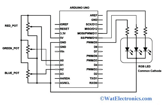
From the figure, A0, A1, and A2 pins of Arduino Uno are connected to the three potentiometers, which represent three colors red, green, and blue. While PWM D9, D10, and D11 pins are connected to the red, green, and blue via 100ohms resistors respectively as shown in the figure. The Arduino Uno generates PWM signals and its ADC (A0, A1, A2) reads the analog voltage across the potentiometers. The PWM signals are the simulating analog output voltage and different voltage levels to the different colors (Red, Green, and Blue) of the LED.

Common Cathode RGB LED using Arduino Uno
Based on the analog voltage across the terminals of potentiometers, the duty cycle of the PWM signals of the pins D9, D10, and D11 is adjusted by using Arduino Uno. As shown in the figure, the intensity of the Red LED is controlled by the PWM/D9 pin. The intensity of the green LED is controlled by the D10 pin. The intensity of the blue LED is controlled by the D11 pin. Finally, the cathode terminal of the RGB LED is connected to the ground pin (GND) of an Arduino Uno. The schematic diagram of common cathode RGB LED using Arduino Uno is shown below.
The datasheet of the RGB LED helps to know the forward voltages of internal LED’s and calculate the actual resistances of the resistors used. We can control the brightness of the RGB LED by changing the resistance of the resistors.
Please refer to this link to know more about LED MCQs
Schematic Diagram of RGB LED
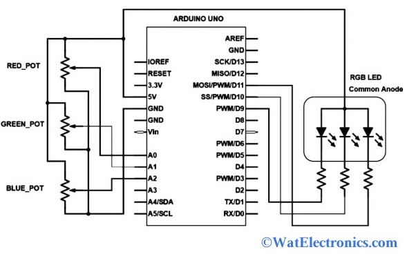
The schematic diagram of common anode RGB using an Arduino Uno is the same as a common cathode type. But the main difference is, the anode terminal of the common anode type is connected to the 5V supply as shown in the figure. The Arduino Uno reads the different voltage levels across the potentiometers for the different colors like red, green, and blue. The schematic diagram of common anode type using Arduino Uno is shown below. While for the common cathode RGB LED, the cathode terminal is connected to the GND pin.

Common Anode RGB LED using Arduino Uno
Thus, this is all about an overview of the RGB LED – definition, types, structure, working, color setting using Arduino Uno, and schematic diagram. The 4-terminal RGB LEDs are used in industrial applications, decorative lightings, torch lights, multi-color lightings, and many more. Here is a question for “What are the Features of RGB LED?”