The initial Clamp meter was invented by Amprobe in the year 1948 and he persisted to do more innovations and presented the device to the world. Amprobe presents multiple types of clamp meters where they range from rugged CAT IV ranked navigator series to the unique Swivel type of clamp meters and also mini clamp meters. The application of clamp meters can be found in many domains as because of their versatility and flexibility. So, this device has many uses. This article clearly shows the working, construction, diagram, specifications, and uses of clamp meter.
What is Clamp Meter?
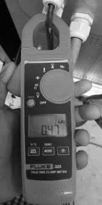
Clamp meters are also termed as Tong Testers. This is the simple device used for equipment testing and for the calculation of live conductor working offering no damage to the other equipment in the circuit. The tool makes use of broad jaws that clamp across the external edge of the conductor in order to deliver the non-contact type of current measurements. These devices are employed for knowing the values of resistance, capacitance values, voltage, continuity, and other measurements.
Initially, clamp meters were invented to be used only for single application functioning tools, whereas the current day clamp meters provide multiple measuring functionalities by providing enhanced preciseness and in some conditions few other exclusive features. The modern-day invented clamp meters consist of the fundamental operations of the digital multimeter like the capability to calculate resistance, continuity, and voltage readings.
Clamp-meters gained more prominence crucially because of two reasons:
Convenience – While measuring, there is no need of switching off the circuit holding current which provides a great boost for efficiency increment.
Safety – By using this device, a lineman can easily bypass the old approach of cutting into a wire and then placing it into the meter’s testing edges to record in-line measurement values. Both the jaws of the clamp meter do not necessarily come into contact with the conductor while measuring the values.
The basic clamp meter diagram is shown as below:

Basic Clamp Meter
Working Principle
Clamp meters are based on the working principle of magnetic induction in order to make no-contact AC current measurements. The flow of electric current across the wire generates a magnetic field and the current transformer which is present internally of the clamp meter detects the magnetic oscillations and transforms the reading to the corresponding AC current value. This is the basic clamp meter principle.
Construction
To construct the clamp meter, there are few parts in the device. This session explains the use of every part and how to clamp meter construction can be done using these parts:
Power
The power switch is utilized to switch ON/OFF the meter.
Jaws or Transformer Clamps
The jaws in the device are used for the detection of the magnetic field when there is current flow across the conductor.
Hold Key
By pressing the hold button, holds the final output on the LCD screen.
Trigger
Either to open or close the clamps, this clamp opening trigger is used.
Positive and Negative Terminals
The positive terminal is utilized to establish a connection between the positive jack and meter cable. While the negative terminal is utilized to establish a connection in-between ground/negative jack and meter cable.
Back Light Button
This button is utilized for lighting up the display that makes easy reading of the values at dark locations or during night time those are displayed on the LCD screen.
Rotary Switch
Through the functional rotary switch, one can select current depending on the kind and range which is used to measure.
LCD Display
With the LCD screen, the measured output value can be displayed.
Clamp Meter Working
A current transformer dependent clamp meter is included with two clamps where those are constructed of Ferrite Iron. Both the clamps are separately covered using copper made coils. These clamps together construct the magnetic core and this measures the measurements. The electro-magnetic law defines that “when there is current flow across the conducting substance, it triggers for the development of magnetic flux”.
Let us consider that the conducting substance from where the current flows through it is treated as the transformer’s primary winding. Because of the current flow in the substance, there will be the development of the magnetic field. When the arm of the clamp meter is positioned to measure, then it operates as the transformer’s secondary winding. The arm’s iron winding of the clamp meter focuses on the magnetic field of the primary coil which is a conductor and so the current has a direct relation to the primary current which is formed by electromagnetic induction. This winding of the clamp meter has a connection with measured circuitry where offers values of current too.
The magnetic field calculating unit is termed as Magnetic Flux which is represented by the Greek letter ‘Ф’. And the current transformer dependent clamp meters generally reacts to AC signals.
Types
There are mainly three types of clamp meter which are:
Current Transformer Type – These types of clamp meters are used only for measuring alternating current (AC) values.
Iron Vane Type – Here, the moving iron vane is affected by the core’s magnetic flux where permits both the DC and AC readings to be calculated and delivers RMS vale for the non-sine AC signals. Because of its physical size, this iron vane type of clamp meter is generally restricted for power transmission frequencies up to the range of 100 Hz. The device is typically attached directly to the display instrument of the pointer and the instrument’s calibration is absolutely non-linear.
Flexible Type – This type of tool is used with Rogowski coil and this measures only AC reading and mainly employed for calculating tight spaces.
Hall Effect Type – Clamp meters those function on hall effect can measure both alternating and direct current readings (AC and DC).
Usage of Clamp Meter
To know how to use a clamp meter, follow the below steps:
- Provide a power supply to the device by connecting the current probe and meter
- To stay back from any circuit damages, select a higher range of values and then gradually reduce the scale reading when the current value is decreased
- Connect the elastic pipe of the probe in the conductor’s region and make sure that the distance between the conductor and the probe should be > 1 inch or = 2.5 inch
- Now, switch on the ammeter across every cable in the winding and find out the current reading. Here, only one reading to be measured at once.
- Find out the current reading on the LCD display.
AC Clamp Meter
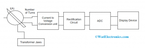
In AC type of clamp meters, they operate based on the current transformer law which is utilized for picking up magnetic flux created when the current flow across the conductor. When the primary current flows across the conductor, then the generated current will be directly proportional to the current through electromagnetic induction from the transformer’s secondary winding. This allows for measuring AC values on the LCD screen. The functional diagram is shown as below:

AC Clamp Meter
DC Clamp Meter
This operation is also used for measuring DC readings.
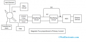
Here, hall elements are considered as sensors to find out DC current due to the reason it is not feasible to use electromagnetic induction approach for specific AC clamp meters. In the below-shown picture, a hall substance is located in the gap which is formed by slicing some section of the transformer jaws. When there is the flow of magnetic flux in proportion to the DC and AC currents in the jaws, then the hall substance identifies the magnetic flux and this flux reading is considered as output voltage.

DC Clamp Meter
The hall substance is a semiconductor device used for the generation of voltage which is in proportion to the multiplication of magnetic field and bias current.
Specifications
The clamp meter specifications mainly vary depending on the manufacturing corporation. For example, the meter which is designed by KYORITSU mainly includes the following.
- DC Milliamp Clamp Meter – The specifications are:
- Model number – KEW 2500
- DC current – 0.01 milliAmp resolution
- Correctness – provides the high-rated measurement of 0.2 percent of accuracy
- Size of the conductor – Ф6mm maximum
- Functional temperature and Humidity – -100C to the range of +50ºC < 85 percent
- Storage temperature and humidity – -200C to the range of +60ºC < 85 percent
- Power Source – R6/LR6 (AA) (1.5Volts) × 4
- Analog output – Recorder: DC 1000milliVolts in contrast to DC 100mA
- Dual display along with the backlight displays both mA measurement and nearly percent of 4-20 mA
- Includes spotlight for illumination of the measurement point
- Dimensions of the device –
111(Length) × 61(Width) × 40(Depth) mm: Display unit
104(Length) × 34(Width) × 20(Depth)mm : Sensor
700mm: Sensor cable
Clamp Meter V/S Multimeter
The crucial differences to be considered between clamp meter and multimeter are as follows:
| Clamp Meter | Multimeter |
| This device is mainly utilized for measuring current readings | Through multimeter, one can find readings of voltage, minimal current, and resistance values |
| Through clamp meters, high current values can be measured | Provides greater accuracy and enhanced resolution |
| Appropriate to calculate machine speed and to know the amount current drawn | Appropriate for electronic operations |
| The added benefit of this device is more efficient | The compactness of the device is an added benefit |
| It has more actions and can be protected from damages | Battery life is not more and this is the drawback of multimeter |
Uses
The prominent clamp meter uses are explained as below:
- Employed for the measurement of high-level currents. Through digital multimeter, there is no scope of measuring 10 Amps of current not more than half a minute and above this time period, the meter gets damaged
- Used in industrial regulations, industrial, household, business equipment, engineering, HVAC, and commercial electric systems
- Clamp meters are also used in remodifying accessible systems depending on the necessity
- Employed to fix troubleshoot issues, perform last circuit checks, and handle electricians when they go through the operation of electrical devices
- Also utilized for the execution of programmed, protective safety along with system troubleshooting
This is all the detailed concept of Clamp Meter. This article has provided a clear description of knowing what a clamp meter is, its working principle, construction, types, specifications, and uses. Furthermore, it is also recommended to have detailed knowledge of clamp meter house-hold applications.