Instrumentation Amplifier is the basic amplifier and the designing of this can be done based on the requirement in different applications. For example, measurement of temperature or it might be humidity for the industrial applications. These measurements must be converted in terms of signals that are in electrical form. Finally, this signal must be provided as the input to this amplifier so that the amplification of the signals can be obtained. The main intention of this amplifier is to eliminate the noise from the circuit. The basic requirements that must be considered while designing of these amplifiers are that it must possess the resistance at the input must be high, the Common-Mode Rejection Ratio (CMRR) must be maintained high with slew rate at high levels but the resistance at output must be low for matching of impedance.
What is the Instrumentation Amplifier?
Definition: A basic amplifier that is designed for amplifying the low-level output signals. It is designed in such a way that while amplification of the signal, it eliminates the noise and the interference. This type of amplifier can be defined as an Instrumentation amplifier.
Instrumentation Amplifier Characteristics
The important points to be noted in this amplifier are listed as follows:
- These amplifiers are known for the amplification of the low-level output signals. Hence it must possess high values of gain.
- It contains a higher amount of input impedance.
- It possesses a low amount of output impedance. To protect the circuit from the effect of loading.
- To generate the maximum outcome such that it can generate undistorted output signals. It must have high slew rates.
- High CMRR is the most important consideration because the input of this amplifier is from the output of the transducer.
In this way, the instrumentation amplifier possesses certain important characteristics in comparison to the other amplifiers.
Instrumentation Amplifier using Op-amp
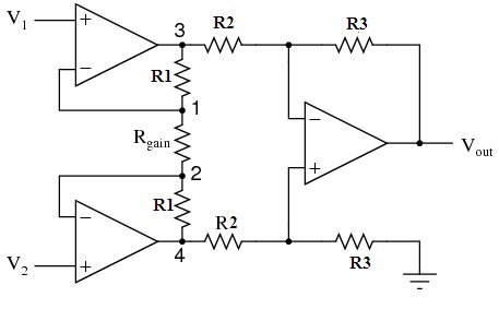
The design of this instrumentation amplifier can be obtained with the basic op-amps. It utilizes ‘three’ op-amps for obtaining instrumentation amplifier configuration. The design can be implemented with the two op-amps but with the ‘three’ op-amps configuration, it is the most widely preferred one. At the input, it consists of two op-amps and at the output, one op-amp is considered.
The inputs are applied to the non-inverting amplifiers present at the input. The output of these amplifiers can be provided as the input to the differential amplifier. Ideally, the gain for the non-inverting amplifiers must be unity. But in this case, the resistors are connected to the outputs of these amplifiers. Hence a potentiometer can be connected in this circuit such that the variable gain can be obtained.
Instrumentation Amplifier Circuit
As discussed earlier, it consists of two non-inverting amplifiers along with a differential amplifier. It consists of resistors with the respective terminals. The intention is to design an amplifier with a high CMRR value along with the maximum undistorted value of signals.

instrumentation-amplifier-circuit
Working
The instrumentation amplifier working requires the following steps.
- The initial amplifiers like non-inverting ones are considered as the buffers. It can be evident from the circuit that for those two buffers three resistors are connected.
- The values of the resistors connected in the circuit will be equal. Except for the resistor R gain.
- At point 1 in the circuit, the voltage will be considered as V1.
- Similarly, at point 2, the voltage will be considered equal to V 2.
- The potential drop generated at the R gain is the difference between the voltages V 1 and V 2.
- Because of this reason the current flow through that point that is through R gain. This indicates that there is no current flow is observed through the feedback.
- Then this results in the same amount of the current flow through resistors that are connected above and below in the circuit.
In this way, the instrumentation amplifier works.
Instrumentation Amplifier Derivation
The derivation for this amplifiers output voltage can be obtained as follows
Vout = (R3/R2)(V1-V2)
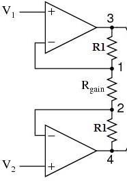
Let us see the input stage that is present in the instrumentation amplifier.

input-stage-of-the-instrumentation-amplifier
From the input stage, it is clear that due to the concept of virtual nodes, the voltage at node 1 is V 1. Similarly, the voltage at the node in the above circuit is V2. Initially, the current through the op-amps considered zero. Hence no current can flow through the resistors.
At node 3 and node 4, the equations of current can be obtained by the application of the ohms law. Therefore the equations are
I = (V1-V2)/(R1+Rgain+R1)….(1)
I= (V1-V2)/(2R1+Rgain)….(2)
As considered there is no current flowing through resistors at the input. The equations at node 1 and 2 are
I = (V1-V2)/Rgain
On equating both the current equations
(V1-V2)/(2R1+Rgain) = (V1-V2)/Rgain…….(3)
The output equation of the differential amplifier can be given as
Vout = (R3/R2)(V1-V2)
(V1-V2) = (R3/R2) Vout
On substituting the above equation in (3)
(R2/R3)Vout/(2R1=Rgain) = (V1-V2)/Rgain
(R2/R3)Vout= (2R1=Rgain) (V1-V2)/Rgain
Vout = (R2/R3)[(2R1=Rgain) (V1-V2)/Rgain]
In this way, this output voltage equation of this amplifier can be derived.
Applications
The instrumentation amplifier applications involve when the environment possesses high noise. The requirement of this amplifier is to achieve high gain. The applications of these amplifiers are as follows
- In the amplification of the signals with the high frequency, these amplifiers are preferred.
- In the systems where the acquisition of the data is required these amplifiers are utilized.
- Practically, in the design of the light intensity meters, temperature control systems these amplifiers are used.
Know more about Instrumentation Amplifier Selection Guide.
Please refer to this link to know more about Positive Feedback Amplifier MCQs & Measurement & Instrument MCQs
Please refer to this link to know more about; Instrumentation amplifier MCQs.
Thus, these amplifiers are preferred, where the physical parameters should be measured. But the input to this amplifier will be from the outcome of the transducers. Because the signal must be converted in to electrical before it must be provided to the amplifier. The circuit of this instrumentation amplifier involves non-inverting and differential amplifiers. Even the virtual node concept is utilized in this circuitry of the instrumentation amplifier. In industrial areas, these amplifiers play a major role. Finally, physical monitoring becomes easier because of these amplifiers. Can you describe why a non-inverting amplifier is preferred over the inverting amplifier in this circuit?