Initially, the birth of amplitude modulation starts by considering a continuous spark transmission and placing a carbon microphone in the antenna lead. This type of positioning has created sound waves, and these got varied both with the intensity and resistance over the transmission. Even there was a disturbing noise, signals can be heard over a distance and that’s up to some hundred meters. So, the introduction of uninterrupted sine signals allowed for continuous transmission and then on AM waves are more considered for sound transmissions. Even there exist various modulating techniques, it stood as standard and there seems to be no interrupt in AM signal transmission.
What is Amplitude Modulation?
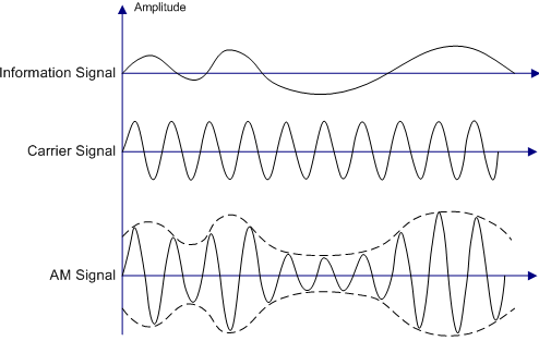
In general, Amplitude Modulation is termed as modulating a continuous transmitting wave that has no intervals and holds the information. While as per the basic definition, it is defined as “A carrier signal which has no information varies its amplitude in correspondence with the change in amplitude of the modulating signal”. The below pictures clearly depict the explanation of the above-stated definition.

basic amplitude modulated wave
The initial one is the message signal which holds certain information, while the second signal has no information and is called the carrier signal. The modulation of these waves results in the AM modulated wave. The dotted line in the AM modulated wave is termed as Envelope and it is in the exact shape of the modulating signal. Through the amplitude modulation, the low-frequency baseband wave is modulated to a high-frequency signal. So, high-frequency signals can transmit over a long distance than that of low-frequency signals.
Representation of Amplitude Modulation
The modulating signal (input signal) is represented as
i(t) = Aicos(2∏fit)
The carrier signal is represented as
c(t) = Accos(2∏fct)
And in the expressions, Ai and Ac represent the amplitudes of two waves while fi and fc are the frequencies of the two waves correspondingly. Solving the two expressions, the modulated wave is represented as
M(t) = [Ai + Ac cos (2∏ (fi + fc)t )]
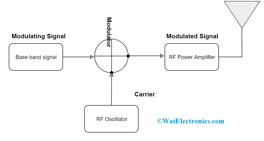
Amplitude Modulation Block Diagram
Here the modulating signals might be an audio or video signal. These are also called as baseband signals as these are modulated with the carrier signals. Carriers are extremely high-frequency radio signals, In general, carrier signals are received from the RF oscillators. These two signals are combined in a modulator. The modulator considers the instant amplitude of the modulating signal and modifies it as per the amplitude of the carrier signal. So, the resultant signal amplitude is the amplitude of the modulated signal. The modulated signal is passed through the amplifier for the amplitude modulation and then transmitted through an antenna or a co-axial cable.

amplitude modulation block diagram
Modulation Index
After the process of modulation, the modulated level of the carrier is calculated, and this exertion is termed as Modulation index. It determines the level of the modulation that a carrier wave undergoes. Below is the modulated signal.
M(t) = [Ai + Ac cos (2∏ (fi + fc)t )]
The above equation can be rearranged as
M(t) = Ac [1 + (Ai/Ac) cos (2∏ (fit)] cos (2∏ (fct)
M(t) = Ac [1 + µ cos (2∏ (fit)] cos (2∏ (fct)
So, here µ is the Modulation index factor and µ = Ai/Ac ——- 1
So, When the amplitudes of both the carrier and modulating signal are known, the modulation index can be known. The resultant modulated wave shows maximum amplitude in the condition cos (2∏ (fit) is 1.
So, Amax = Ai + Ac
Similarly, the resultant modulated wave shows minimum amplitude in the condition cos (2∏ (fit) is -1.
So, Amin = Ai – Ac
Combining and solving the maximum and minimum amplitude equations, the amplitude of the carrier signal can be known, where
Amax + Amin = Ai + Ac + Ai -Ac = 2Ac
Ac = (Amax + Amin)/2
Whereas Amax – Amin = Ai + Ac – (Ai -Ac) = 2Ai
Ai = (Amax – Amin)/2
With the above Ai and Ac equations, the ratio of these can be calculated as
Ai/Ac = [(Amax – Amin)/2]/[(Amax + Amin)/2]
So, µ = (Amax – Amin)/(Amax + Amin) ————-2
Therefore, the Modulation index can be represented in the form of either equation 1 or 2. When represented in the form of a percentage, it is called a percentage of modulation. When the value of µ is < 1, it is called under-modulation and that wave is called an under-modulated wave. And, when the value of µ is > 1, it is called as over-modulation and that wave is called an over-modulated wave.
Types of Amplitude Modulation
Amplitude modulation is classified as three types and they are
Double Sideband Suppressed Carrier (DSB – SC)
Here, the frequency spectrum of the modulating signal is located symmetrically below and above the frequency of the carrier signal. Sidebands correspond to lower and upper frequencies of the input information signal. The upper sidebands are the frequency components higher than that of the carrier ones, while lower sidebands have lesser frequency components than that of the carrier frequency.
The amplitude modulated signal equation for DSB- SC can be written as
DSB-SC (t)= Accoswct + Ai/2 cos (wc + wi)t + Ai/2 cos (wi – wc)t
Of the three terms in the equation, the first one corresponds to the carrier signal, the second term signifies to modulating signal where the frequency is shifted left by wc and the third term signifies to modulating signal where the frequency is shifted right by wc.
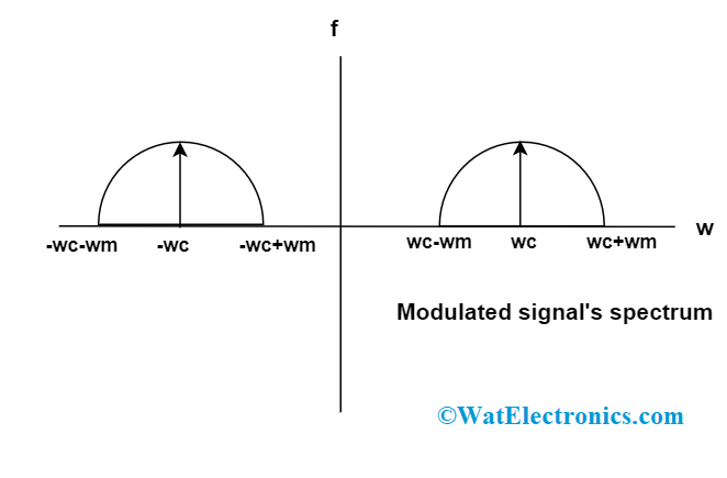
The DSB-SC modulated wave spectrum is represented as

DSB SC amplitude-modulated spectrum
The modulation index and bandwidth of DSB-SC is as follows
DSB-SC (t)= Ac (1+ µ coswit) coswct
Bandwidth is defined as the difference that is between maximum and minimum frequencies of them the resultant modulated signal.
Bandwidth = (fc + fi) – (fc- fi) = 2fi
So, bandwidth is double the bandwidth of the modulating signal. In DSB-SC, the modulation process can be done easily, and it requires no filtration for sidebands.
Single Sideband
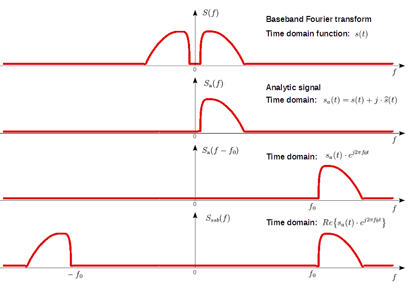
In this, only one sideband is transmitted through an antenna and is called as singles sideband amplification. It has either upper or lower sideband. The SSB modulated wave can be obtained by passing a DSB wave through a bandpass filter. The bandpass filter either filters upper or lower sidebands of DSB SC wave as shown in the below figure.

single sideband
Here, the bandwidth of the modulated wave is equal to the bandwidth of the modulating signal. It can save power because only one sideband is transmitted.
Vestigial Sideband
The bandpass filter does not hold the ability to cut off the frequencies which are external to the cut off region. And this problem may allow causing some disturbing noises. To eliminate this problem, vestigial sideband modulation is implemented. Here, either of the sidebands (either upper or lower) is transmitted and some portion of the other is transmitted.
The bandwidth of the VSB signal lies in between the SSB and DSB-SC signals and it is
Bandwidth = fi + (25%) fi
These are the three types of amplitude modulation techniques.
Differences between AM and FM
At first, both amplitude and frequency modulations are used to transmit information through the technique of varying the carrier signal.
As per the definition, in amplitude modulation, the amplitude of the modulating signal varies as per the carrier signal’s amplitude. The AM signals make use of lower frequencies to transmit information to long distances. While in frequency modulation, the frequency of the modulating signal varies as per the carrier signal’s amplitude. The bandwidth of the frequency-modulated signals is higher than that of AM modulated signals that help to transmit better quality voice signals.
| Amplitude Modulation |
Frequency Modulation |
| The first modulated wave was transmitted in the year the 1870s | The first modulated wave was transmitted in the year 1930 |
| The radio wave is defined as a carrier signal and both phase and frequency are maintained at the same | The radio wave is defined as a carrier signal and both phase and amplitude are maintained at the same |
| The AM signals can be transmitted to long distances but have lesser sound quality | The FM signals can be transmitted to long distances and have good sound quality |
| These waves lie in the frequency range of 535 to 1705 kHz | These waves lie in the frequency range of 88 to 108 MHz |
| Highly suspected of noise signals | Less suspected to noise signals |
Applications of Amplitude Modulation
The applications are
Amplitude modulated waves are utilized in a wide variety of applications and few of those to be described as below.
To broadcast transmissions – AM waves can be used to transmit long, short and medium wavebands. The demodulation process is also simple, and this implies that radio receivers which hold the capability to demodulate are manufactured simply.
AM waves are also used to transmit very high-frequency waves such as airborne applications. These are also implemented for the ground to air radio transmissions and also two-way radio communications.
Single sideband amplitude modulated waves are used for high-frequency radio links. Using a minimal bandwidth and offering more effective utilization of the broadcasted power this kind of modulation is still utilized for various point to point high-frequency links.
AM is extensively utilized for data transmission ranging from short wireless links like wireless networks to cellular telecommunications and many others. Successfully it is developed using two carriers which are 90° out of phase.
Further, the applications of amplitude modulation are
- Air traffic control radios
- Keyless remotes
- Broadcasting of TV signals
- Electronic communications
Advantages & Disadvantages of Amplitude Modulation
Any of the technology or system has its advantages and disadvantages. So, here the advantages and disadvantages of amplitude modulation are
Advantages
The advantages are
- Both modulation and demodulation processes are simply implemented
- Cost is also economical as fewer circuits and diodes are used
- Can transmit signals to longer distances
- The waves have lesser bandwidth
- Less complicated
Disadvantages
The disadvantages are
- Minimal efficient for power utilization as a DSB-SC modulation process consumes more power
- Even not efficient in bandwidth utilization too.
- Less sensitivity to noise signals, so more prone to noise disturbances
- Reproduction is not greatly reliable.
Please refer to this link to know more about Amplitude Modulation MCQs
FAQs
1). What is the use of amplitude modulation?
Amplitude modulation is used in the cases when there is a requirement for multiples changes in the amplitude of the input signal and mainly used in electronic transmissions.
2). What is modulation in simple words?
It is the method of modifying a waveform (carrier) signals as per the input signal that has to be transmitted.
3). What is the bandwidth of amplitude modulation?
The bandwidth carried by the amplitude modulated wave is double the bandwidth of the modulating signal.
4). Which one is better FM or AM?
Each of the modulation techniques holds its advantages and disadvantages and no one seems to be better than the other.
5). Why is modulation needed?
To decrease the antenna size and enhance the bandwidth of the signals, the modulation process is implemented.
Thus, this is all about an overview of amplitude modulation that can be widely used in many commercial and personal applications. Know more about the concepts of what are the other types and derivatives of amplitude modulation?