In an electric circuit many times it is desirable to restrict the current, which can either be done by reducing the voltage or increasing the resistance in the circuit (Ohm’s Law). A rheostat is a device that facilitates this. The word rheostat is derived from the Greek language meaning changing stream (current). It is a must for any electrical laboratory/workshop in order to carry out experiments under variable current and voltage conditions. This is done by inserting a variable resistance in the circuit. A smooth control provided by this is very helpful in making precise observations. Many types of rheostats are available and are in use in power/electrical circuits, but here we shall limit ourselves to sliding type linear rheostat which is most commonly used in electrical/power circuits.
What is a Rheostat?
Definition: A rheostat is a smoothly variable resistance used in order to change the flow of current in an electric circuit. A British scientist namely Sir Charles Wheatstone was the person who gave this Greek word meaning the current controlling device.
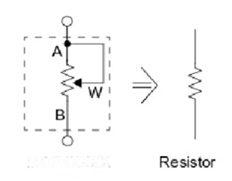
Rheostat
Rheostat Function
From basic electrical engineering we know that voltage, current, and resistance are interdependent and can be represented as:
R = V / I
Where ‘R’ is the resistance, ‘V’ is the voltage, and ‘I’ is the current. And therefore, in order to change the current, we must either change the voltage or the resistance. The voltage source is generally fixed and cannot be changed, so we are left with resistance only.
It is a resistance that can be varied continuously from zero to its maximum value. Further, we know that the resistance is directly proportional to the length of the wire and inversely proportional to the diameter of the wire. The material also plays its part as different materials have different resistivity. The length and diameter of the wire can easily be chosen depending on our requirements.
As the flow of current thru a resistance is associated with the rise of temperature. Since the temperature rise may also result in a change in resistance. In a rheostat, it is always desirable that the resistance remains nearly content through a wide range of temperatures. A material known as ‘Constantan’ which is an alloy of copper and nickel is used for this purpose as its resistance remains stable for a wide range of temperatures.
Construction-wise, it has two fixed points/terminals which are the ends of a constantan wire wound over a ceramic tube. The third point is a wiper point which moves (manually or motorized) over this wound wire. As we move the wiper point connected to the circuit, we can vary the resistance. It can be linier type or the rotary type as per its construction.
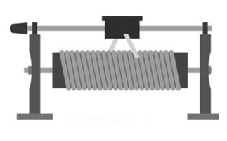
Construction
A pictorial view of a linear type is shown above which is self-explanatory.
Symbols
Various standards show rheostat symbols differently, however the most commonly used are shown above.
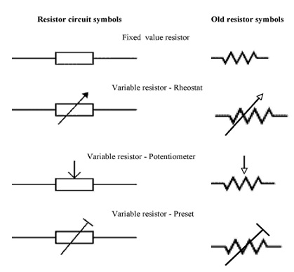
Rheostat Symbols
Rheostat Working
In order to understand the working of this, let us take an example of a rheostat which is connected in series of a DC motor field. As for the performance of a DC motor largely depends on the field current has to be adjusted precisely and it is connected in series with the field can do it well.
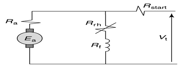
Rheostat Connection Diagram
As shown in the connection diagram above. It may be added that although only a fixed point and variable point is generally required there are conditions where all the three points/terminals are utilized.
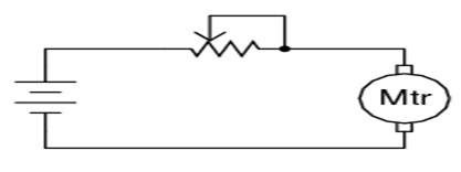
Circuit with Two Points
In the above figure, it will be noticed that the wiper point and one of the fixed points is connected, this is done in order to eliminate the possibility of motor armature/field getting open-circuited, should the variable/wiper point lose contact with resistance or rheostat (being a moving point). Similarly, all three points of this are utilized when it is used as a potential divider.
Uses/Applications
The rheostat applications include the following.
- Used in electrical workshops/testing labs to study the performance of various equipment’s/circuits under various current and voltage conditions
- Used in a wheat stone bridge to find out the unknown parameters by balancing the bridge.
- Used as a dimming device in lighting circuits.
- May be used as a variable resistive load.
- May be used as a voltage divider.
Difference between Rheostat and a Potentiometer
The basic difference between these two is their power handling capacity.
| Rheostat | Potentiometer |
| A rheostat being able to handle higher current and voltage is mostly used in electrical application like motor control, light control | A potentiometer is mostly used in electronic applications like electronic regulators, reference setters, etc.
|
| Construction-wise, it may use various mediums depending upon the current capacity, the most common being the wire wound rheostat. | A potentiometer is either wire wound or maybe a Carbon/Graphite resistance. |
| In this, all three points may or may not be used. | In a potentiometer, all three points (two fixed and one variable) are used |
| The range is not available in the rheostat. | Potentiometer also is known as ‘Pot’ comes in many verities and shapes. For large range and precise settings, we have ten turn pot. We may also have digital potentiometers using electronic components. |
| Rheostat due to high power loss in the form of heat has limited application. Nowadays most electronic components like SCR, MOSFET, etc are being used.
|
Application wise almost all electronic equipment where settings and control are required to use a potentiometer. |
FAQs
1). What is rheostat made of?
Various mediums can be used for rheostatic control, the most common is a resistance wire made from constantan offering stability over a wide range of temperatures.
2). What is the difference between rheostat and potentiometer?
The basic difference between rheostat and potentiometer lies in its power handling capacity. A rheostat is suitable for handling high current and voltage while a potentiometer can handle current in the low range say Ma. and Mv. Range.
3) What is the principle of rheostat?
The principle of rheostat is based on Ohms law which says that the flow of current in a conductor is directly proportional to the voltage applied and inversely proportional to resistance, physical conditions remaining constant.
4) How do you test a rheostat?
A rheostat can be tested by measuring the resistance between any of the two fixed and variable points. The change in resistance should be proportional to the movement of the wiper point as we move it from minimum to maximum. The value thus obtained should conform to the rated value.
5) Why does rheostat have three terminals?
Some specific circuit requirement calls for the usage of all the three terminals, like in the case where rheostat is used as a potential divider and where we wish to eliminate the possibility open circuit due to wiper movement.
Thus, this is all about an overview of the rheostat. It is very important and useful equipment, although it is being replaced by electronic devices but has not found its replacement in many basic functions like in Wheatstone bridge, Rotor starters, DC motor starters, etc. As testing equipment, it is an asset as it is simple, rugged, and cast effectively.