The digital circuits made of logic gates as the basic devices. This leads to the formation of combination circuits and sequential circuits. The circuit design must have a memory element present in it. This element stores the data required for processing the code and the stored information is needed for the program during computing. The memories are treated as the key components in digital electronics. These storage devices are termed as a latch. Individual logic gates don’t have any capability of storage. But several gates connected make its storage capacity. Each gate stores a single bit of binary information. These memory elements are classified into two types. They are Flip Flops and Latches. Both are formally known as Bistable Multivibrators. Because of two possible states in it either logic 0 or logic 1. The basic difference between these sequential circuits is the clock signal implied. The unclocked flip-flops are referred to as latches.
What is Latch?
The Latch is a term used for the flip-flops without any clock signal applied for operation. The reason behind this is that the latches are capable of changing its states from 1 to 0 or 0 to 1 based on the input signal received that is either Set or Reset.
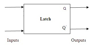
Latches (Block Diagram)
This type of sequential circuit can respond to any type of input signal applied. It keeps a check on the signals applied and responds to it immediately. The functionality of the latch is dependent on the enable signal and independent of the clock signal. The change in the states is sensitive to the level of the pulse applied rather than edges.
Types of Latch
The latches are classified based on the input signals applied.
- If the input applied is ‘Active High’. Then at this stage, the resting state of the set and reset signal is low. based on the requirement to change the output the signals applied must be in the high state. These are known as ‘Active High input Latches’.
- If the input applied is ‘Active Low’. Then the set and reset signals are resting at the high state. To be able to obtain the desired outputs the signals must be applied of low sate. these types of latches are referred to as ‘Active Low input Latches’.
Further, the latches are classified based on the ability to change in output to the applied input.
- If the latches are capable enough of responding to the inputs to obtain the required outputs. For every input, a pulse applied to the change in the output is observed. These types of latches are known as Asynchronous Latches.
- If the change in output noticed because of the influence of the Enable signal in the circuit. the enable signal can be a clock either. These types of latches are known a Synchronous Latches.
S-R Latch
An asynchronous latch that works based on applied set and reset signals without relying on control signals is referred to as S-R Latch. It produces two outputs that are labeled as Q and Complement of Q. These gates are constructed by using the universal gates NAND or NOR.
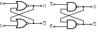
S-R Latch using NOR and NAND Gates
The gate constructed by using cross-coupled NAND gates is of active Low type S-R gate. The active-low can be converted to high by including the inverters at the inputs. By using two cross-coupled NOR gates one can produce an active high S-R gate.
The operation of the S-R latch based on the inputs applied is as follows:
- When SET = HIGH, Q=1. When RESET = HIGH, Complement of Q=1 (i.e.,Q=0).
- When SET=RESET= LOW, there is no change evident in the latch state. This state is also referred too as the prior state before the application of inputs.
- when SET=RESET=HIGH. The outputs Q and complement of Q may be high or low. The situation of the gates is unpredictable during such inputs. This type of state is defined as Indeterminate or Invalid state. This leads to the ‘Race Around Condition’.
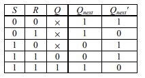
Truth Table (NAND Gate)
The above truth table information is for S-R Latch constructed using NAND gates. Similarly, the truth table of this latch using NOR gates is
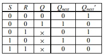
Truth Table (NOR gate)
The word reset also stands for clearing because if the output state is 1 it will be reset or cleared to 0. This type of resetting is not possible in gated S-R latch. Because in such gates the output states have relied upon the application of the external pulse.
Gated S-R Latch
Generally, an S-R latch designed its behavior is sensitive to the inputs. To make it more flexible an S-R Latch circuit is made synchronous by adding the property of enable signal. If the Enable signal is HIGH then the operation is performed based on the inputs applied and the change in the output is detected.
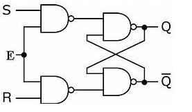
Logic Diagram
If the applied Enable signal is LOW. Then the inputs are ineffective and no change in the output states is detected. The enable signal used may also be a clock signal.
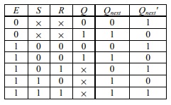
Truth Table
Usually, the NAND implementation of S-R is in the active low type.
- when ENABLE=1, the circuit is enabled. The S and R inputs behave in the active HIGH manner.
- when ENABLE=0, the latch maintains the previous outputs in spite of the change in the inputs of S and R.
- In the gated latches the signals applied for is Enable, Control or it might be Clock.
D-Latch
The problematic condition of the S-R latch is the de-assertion of S and R inputs at a similar timing. Such a condition of the indeterminant state is removed in D-latch. These circuits are constructed by using universal gates.
The implementation of this latch using NAND gates is
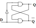
D-Latch
This type of latches doesn’t require any separate S or R inputs. This can be constructed by using single input ‘S’ and the other input R is obtained by connecting the inverter at the input. This single input can be referred to as D. The extension of the S-R latch is known as D-latch.

Truth Table
As the purpose of the S-R latch is to set or reset but the D-latches are capable of storing a single bit of information.
Gated D-Latch
The D-latch in which the output states conditions rely on the Enable signals is referred to as Gated D-Latch. The output generated is the reflection of the applied input. These latches are also known as ‘Transparent Latches’.
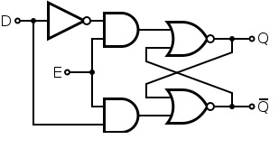
Gated D-Type
From the above circuit, the following points can be concluded as
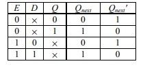
- When D=1, the S is at 1 and R will be 0. Hence the latch is SET to 1 once the ENABLE=1.
- When D=0, the S is at 0 and R will be 1. Hence the latch is RESET to 1 once it is ENABLED.
The truth-table for the gated D-Latches is
Truth Table
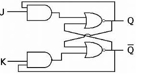
J-K Latch
The Latches in which the output is fed back to the input is known as a J-K latch. The condition of the state under ambiguous has been eliminated in this circuit. When both the inputs J and K are HIGH the output states get toggled. It is similar to the basic S-R gate. The only difference is the feedback path application.
J-K Type
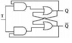
T Latch
The short-circuiting of the inputs of J-K latches are resulting in the formation of T-Latches. If the input applied is HIGH then the output states results inn Toggling.
T Type
Advantages and Disadvantages of Latches
The advantages of the latches are
- The latches designed by using logic gates accommodate less space.
- The non-sequential behavior of the latches leads to stealing the cycle to complete the operation when it is required.
- These are known for responding to the inputs applied and they are quick by nature.
- It requires less amount of power.
Like advantages, there are certain disadvantages of latches. Due to the desertion of the bits, the situations of toggling and race-around conditions are encountered in the circuit. Due to the level sensitivity, the analysis of latches in the circuit gets complicated.
Please refer to this link to know more about Time Division Multiplexing MCQs & Latches MCQs
Applications of Latches
The applications of these basic digital elements are
- These circuits are known for storing the information in the form of bits. These are known as memory elements.
- The usage of pulse latches follows the same behavior of flip-flops but good enough to generate a quick response.
- In the two-phase synchronous systems to avoid the transit count, the data latches (D-Latches) are used.
- It is widely used to store the data and the codes for computations.
FAQs
1). What is the Difference Between Latches and Flip-Flops?
The basic difference between the latches and the flip-flops is that the latch is sensitive to the level of the signal applied whereas the flip-flop is Edge sensitive.
2). Why Do We Use a Latch?
The feedback path is present in the latches which helps to retain the information stored in it. Even produce faster responses. Hence the latches are used.
3). Why Flip-Flop is called Latch?
The logic gates present in the latches are provided by the Enable signal to achieve the synchronous operation. This Enable signal can be a Clock. These gated latches sometimes referred to as Flip-Flops.
4). Why Latches are called Memory Devices?
The latches are known for their behavior of Bistable Multivibrator. It consists of two states 1 and 0. These bits are stored in the gates. hence these are known as memory devices.
5). Is Latch Better than Flip-Flop?
The application of additional control signals along with inputs so that the generation of the output is dependent o the applied control signals. Still, it is time-consuming. To obtain the quick realizations latches are better than flip-flops.
Know more about Hamming Code.
Know more about Signals and Systems MCQs.
As it is discussed that the latches are classified under the category of the sequential circuits. Its classification is based on the behavior of the inputs and their response is based on the Enable signal. After the overview of these latches can you explain where the latches are preferred over flip-flops?