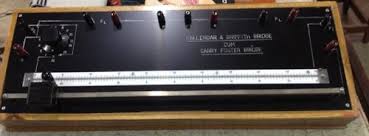
Carey Foster bridge is basically used to calculate the difference between the resistance of two elements. It was invented by scientist Carey Foster in the year 1872. It is one of the variant forms of a wheat stone bridge which is used to measure unknown resistance by balancing two legs of a bridge circuit, in which one leg consists of the unknown component. It can be seen that the wheat stone bridge works on the balancing concept. The same concept is used in Carey Foster bridge with small modifications. This bridge has a number of applications especially in designing the equipment. The difference in resistance calculation is important while calculating the losses and efficiency.
What is a Carey Foster Bridge?
Carey Foster bridge is a circuit that measures fundamentally the difference between the resistance of two elements. This one of the variants of a wheat stone bridge which is used to measure the unknown resistance.

Carey Foster Bridge
Carey Foster Bridge Circuit
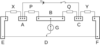
The circuit diagram of a Carey Foster is shown below. In the diagram, A, B, C, F, and E are the metallic strips. These metallic strips are designed such that their resistivity is low. This means that let us say for metallic strip E when connected to X, the resistance of the contact is almost negligible. This is done so as to obtain accurate measurements. The X, P, Q, and Y represent the resistances.

Carey Foster Circuit Diagram
These are the resistances for which the difference should be measured. That means that we are going to calculate the difference in the resistances between X and Y. Similarly we are going to calculate the difference in resistance between P and Q. From terminals, A and C a battery or a cell is connected along with a small switch.
Whenever the switch is closed, the current starts flowing, inside the circuit. G represents a galvanometer, with a jockey connected to its end. The jockey can be slide in the part EF along with D. It must be noted that the resistance of the part ED, can not be ignored. It has a significant amount.
Working Principle of Bridge
The basic fundamental functioning of the Carey Foster bridge is to measure the difference in the resistances. Let us say we want to calculate the difference in resistance between X and Y. In that case, the resistance of one element must be known. It could be X or it could be Y. That means only one resistance value is unknown. To further analyze, let us assume that the resistance of Y is unknown.
So we are going to calculate the difference in the resistance between known parameter X and unknown parameter Y. Once we get the difference X-Y since the X value is known, the Y value can also be easily known. When the switch is closed, the circuit forms a closed path along with the galvanometer. The jockey of the galvanometer is adjusted such that, the galvanometer shows zero deflection.

Carey Foster Working
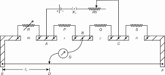
When the galvanometer shows zero deflection, it means that the circuit is balanced. In other words, no current is flowing through the galvanometer. Let the distance between E and D be represented as l1. Then the values of X and Y should be swapped. It means that X becomes Y, and Y becomes X. Then the jockey of the galvanometer is moved to one more point such that, again its deflection is zero. Let us assume it move towards the right side, and at that point the let the distance be l2.

Now the difference in the resistance X and Y is given as X-Y= Resistivity of l1(l2-l1). This is the desired equation. This represents the resistance per unit length. When the switch is closed the circuit forms the bridge circuit as shown above. Vg is the galvanometer as shown before. Between A and D we have R1 which is equal to X. Between A and B we have R3 which is equal to P. Between B and C we have Rx, which is equal to Q. And between C and C we have R2 which is equal to Y. Hence the unknown value, in this case, is Q.
Now once the galvanometer reading is zero, we say that the bridge is balanced. This means that, R1*Rx= R3*R2. Or we can also say that, X*Q=P*Y. Hence the Carey Foster bridge takes the form of a wheat stone bridge. We should also consider the resistance of the elements l1 and l2 in the balanced expression. The overall expression is shown above. It may be noted that in place of X we have written R and in place of Y we have taken S. r represent the resistivity of the length l1.
Calibration of Sliding Wire
The calibration of sliding wire is important for accurate measurements. In order to have completer calibration, the necessary values are the resistance of the wire, the resistance of the unknowns, P, and Q. The total resistance of all the settings. The resistance between the zero setting and the galvanometer branch. Apart from these, the temperature coefficients of all the coils are also necessary.
Based on the measurements, the maximum deviation is calculated between each point. Initially, the measurements are started with known X and unknown Y. Then they swapped. While taking all measurements it is taken care that the deviations must be less than 0.00014 ohms, or in other words 7 parts in 10000000 of the total resistance.
Variations due to the changes are accepted up to 0.0001 ohms. For these variations, it must be noted that the galvanometer jockey settings are made keeping in view of the balancing of the pointer. For every measurement, the variations are noted and made sure that the variations are less than the desired value. In this way, the calibration of the slide wire is done.
Advantages
The main advantages of Carey Foster Bridge are
- It gives an accurate measurement of the difference in the resistance. Whenever the Carey Foster bridge is used for measurement, it gives precise results as compared to other equipment.
- Only one unknown resistance is sufficient to measure the difference. Since this equipment works on the balancing principle, only one unknown resistance is sufficient to measure the difference. Later the known resistance is swapped with the unknown.
- Less maintenance and less cost. This equipment has no expensive parts. Most of the parts are less in cost and easily available.
- Less chance of human error. As this method, depends on the deflection of the pointer by a galvanometer, so there is very little chance of any error. Hence this equipment is more precise.
Disadvantages
The main disadvantages of Carey foster bridge are
- The slide wire needs to be calibrated. After regular use, the slide wire has to be calibrated to avoid errors.
- Aging of the coil. With time, the characteristics of the delicate part may not be the same. Like the resistance elements and galvanometer. Hence they need to be replaced.
- No scope for digital measurement. This device cannot be made to be used for digital display.
Applications
The applications of Carey Foster Bridge are
- This bridge circuit is used to measure the difference between two resistances
- The circuit can also be used for comparison of equal resistances
- The circuit can be used to find the specific resistance of the wire
- The circuit can be used to measure unknown resistance.
Hence we have seen the working principle and different characteristics of the Carey Foster bridge. As we have mentioned, it is a purely an analog method to measure the difference in the resistances. It can be thought that how can we use electronic equipment along with Carey Foster bridge for more accurate and precise measurement?