The band stop filter is a type of frequency selective circuit, that works exactly opposite to the bandpass filter. The name itself shows that it stops or rejects the particular range of frequencies of a signal. This filter is designed with the low pass filter and high pass filter, which are connected in parallel to allow high and low-frequency components. The band stop filter allows frequency components below the cut-off frequency and above the cut-off frequency. The cut-off frequency of the low pass filter is denoted as fL and the cut-off frequency of the high pass filter is denoted as fH. As the band stop filter contains two cut-off frequencies for low and high-frequency ranges, it depends on the components used in the circuit. This article gives a complete description of the band stop filter.
What is Band Stop Filter?
The filter that allows above and below the particular range of frequencies and rejects all other frequencies of a given input signal, is known as band stop filter. It is also known as a band-reject filter or band elimination filter or notch filter. It allows all the frequencies below and above the cut-off frequency of low pass and high pass filter circuit. Since this circuit is designed using low pass and high pass filter circuits. This type of filter is mainly used to reduce the distortion in the signal.
Band Stop Filter Circuit
The RC band stop filter circuit is shown below.
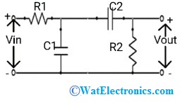
Band Stop Filter Circuit
When the input signal is applied, the high frequencies are passed through a high pass filter and low frequencies are passed through a low pass filter. The output voltage Vout drops at the high frequency of the high pass filter and at a low frequency of the low pass filter. These two filters are connected in parallel to allow all the high and low frequencies of a signal without any obstruction. The range of frequencies between the fL and fH is attenuated.
It allows the frequencies below the fL and above the fH. The frequencies between fL and fH are attenuated, which represents the stopband.
Band Stop Filter Design
The transformation characteristic of the bandstop filter can be improved by using high pass filter and low pass filter circuits. An inverting voltage follower with Av = 1 isolates these low and high pass filter circuits. The output of these circuits can be added by using an op-amp that acts as a voltage summer or voltage adder.
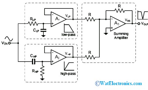
Band Stop Filter Design
The op-amps used to improve the voltage gain in the filter. The voltage follower in the two filter circuits can convert the voltage gain of the basic inverting op-amp of Av =1+(Rf/Rin). This can be designed using inverting op-amps to improve the voltage gain and to achieve amplification of the signal is shown below.
Theory
The band stop filter theory can be understood by using the block diagram shown below.
From the block diagram, we can observe that a band stop filter is a combination of a high pass filter and a low pass filter connected in parallel instead of series. The applied input signal is applied to the filter, the low pass filter allows only the low frequencies whereas the high pass filter allows the high frequencies of the signal. So, the bandstop filter will have two cut-off frequencies named as lower cut-off frequency and upper cut-off frequency.
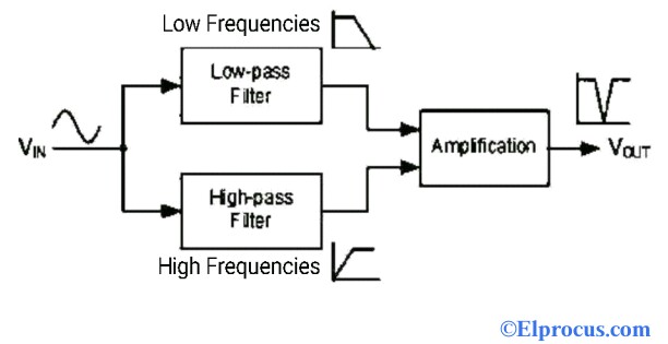
Block Diagram
The low pass filter allows the frequencies below its cut-off frequency while the high pass filter allows the frequency above its cut-off frequency. These two cut-off frequencies are predetermined based on the component values used in the circuit. The bandstop filter doesn’t allow the frequencies between these two cut-off frequencies and are attenuated or rejected. It has a stopband and one passband. The final output from the high pass filter and low pass filter is amplified by using an operational amplifier (op-amp) to improve the voltage gain.
Band Stop Filter Calculator
This is a second-order filter because of 2 cut-off frequencies (lower and higher) with a bandwidth of -3dB that points between upper and lower points. So, the bandwidth can be (fL – fH). The bandwidth can be calculated by taking the difference between lower cut-off frequency fL and upper cut -off frequency fH
Bandwidth = fL – fH
The center frequency is the square root of the difference between the cut-off frequency of low pass filter and the cut-off frequency of high pass filter
fc = √( fL x fH)
Where fc = center frequency
fL = cut-off frequency of low pass filter
fH = cut-off frequency of high pass filter
Consider the RC band stop filter to calculate the cut-off frequency.
The cut-off frequency of the low pass filter is given as
fL = 1/2πR1C1
The cut-off frequency of the high pass filter is given as
fH = 1/2πR2C2
The quality factor Q of the circuit can be calculated as
Q = fc/bandwidth
The band stop filter circuit using R, L, and C is discussed below.
This filter allows a particular range of frequencies, which are above and below the cut-off frequencies of high pass and low pass filter circuits. It blocks the frequency components between the low and high-frequency ranges. The circuit using R, L, and C is shown below.
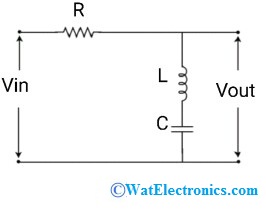
RLC Circuit
The passive elements R, L, and C are connected in series. The input voltage is applied across the resistor and the output voltage is obtained across the inductor and the capacitor. This filter allows all the high and low-frequency components with respect to the cut-off frequency. At low-frequency range, the capacitor becomes an open circuit and the inductor becomes a short circuit. At the high-frequency range, the capacitor becomes a short circuit and the inductor becomes an open circuit.
This circuit behaves as an open circuit at high and low-frequency ranges due to the capacitor and inductor are connected in series. Hence, at the mid-frequency range, the filter behaves as a short circuit and is blocked by the filter. The components used in the circuit determines the lower and higher cut-off frequency. The transfer function of the circuit is,
H(jω) = j(ωL – 1/ωC) / (R+(jωL – (1/ωC)))
Where ω = 2πf = angular frequency
Notch Filter (Narrow Band stop filter)
The band stop filter with a narrow frequency response is known as a notch filter. It is designed to reject or block a particular band of frequencies and increases the selectivity of the filter. The quality factor ‘Q’ is very high when compared to the bandpass filter. It is widely used to reject the specific frequency bands in reducing electrical noise, graphical equalizers, synthesizers, communications, biomedical applications, and many more.
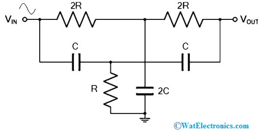
Notch Filter
The basic notch filter is designed by using two RC sections in the form of T. This design is called twin-T notch filter or twin-T configuration or parallel T configuration. If the notch filter provides maximum attenuation at a specific frequency, then it is called notch frequency fn, is given as
fn = 1/4πRC
The figure shows that the resistors and the capacitors in the upper T-sections form the low pass filter circuit. The lower T-section forms the high pass filter circuit with a resistor and a capacitor.
Frequency Response
The frequency response of the band stop filter is shown in the below figure. The frequency response is drawn between frequency vs gain.
In practice, the switching mechanism of the capacitor changes the output characteristics of high pass and low pass filters and are not similar to the ideal filter. The passband gain of this filter should be equal to the gain of the low pass and high pass filter.
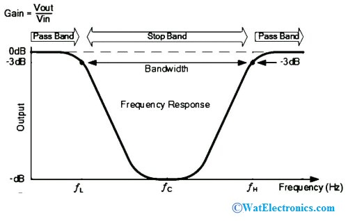
Frequency Response
In an ideal band stop filter, the pass band gain should be Amax and the stop band gain should be zero. But it is not possible in practice due to the transition region between the high and low pass filter sections. The pass band ripples and the stop band ripples can be measured by using,
Stop band ripple = – 20 log10(δs) dB
Pass band ripple = -20 log10(1-δp) dB
Where δp = pass band filter magnitude response
δs = stop band filter magnitude response
For example, if the lower cut-off frequency (low pass filter) is 500Hz and the upper cut-off frequency (high pass filter) is 1000Hz, then the band stop filter works by allowing the low frequencies below and up to 500Hz and high frequencies above 1000Hz. The frequencies between 500Hz and 1000Hz are attenuated. The band stop filter gives a wide frequency response when compared to the band pass filter.
Characteristics
The ideal characteristics of the band-stop filter, which are opposite characteristics of band pass filter are shown below.
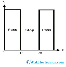
Band Stop Filter Characteristics
This filter allows the frequencies of a signal in a particular range i.e., above and below the cut-off frequency. So, it has two passbands and one stopband. The stopband represents the attenuated frequencies, ranges between the two cut-off frequencies. While the two passbands the frequencies below and above the cut-off frequencies of low pass and high pass filter circuits.
The main characteristic of the band stop filter is, it allows all the frequencies from zero to up to cut-off frequency and allows all the frequencies above the cut-off frequency. This type of filter the frequencies between the upper and lower cut-off frequencies
Band Stop Filter Example
Find the resistance required for an RC band stop filter with a center frequency of 120Hz and, the capacitance of 0.33micro farads.
We can find the resistance of this filter by using the formula,
fc = 1/2πRC
R = 1/(2πfcC)
R = 1/(2π x 120 x 0.33 x 10^-6)
R = 4kilo ohms.
Hence, a resistor of 4kilo ohms is required to design the RC bandstop filter with 120Hz center frequency and 0.33 micro Farads capacitance.
Applications
The bandstop filter applications include the following.
- Used in telephone technology to reduce noise and provide DSL internet services
- Used in amplifiers of the electric guitars to reduce hum and amplify the signal
- Used in electronics and communication systems to reduce distortion in the signal
- Used in audio and radio applications
- Used in optical communications to eliminate the distortion due to the interference of frequency signals.
- Used in digital signal and image processing systems
- Used in biomedical devices like ECG to reduce noise.
Know more about Matched Filter MCQs, Band Pass Filter MCQs , Low Pass Filter MCQs.
Thus, this is all about the bandstop filter – definition, circuit, design, theory, calculations, frequency response, characteristics, narrow band stop filter, and applications. The purpose of this filter is to reject the wide band of frequencies. Here is a question for you, “What are the advantages of a notch filter? “