There are many electronic circuits that are used for signal transmission. It can be an amplifier or modulator or it might be anything related to the signal strength enhancement. These devices are known for accepting the signal at a certain defined range of voltages. If the signal applied has an amplitude value greater than that of the range described this results in distortion or it may destroy the components present in the circuit. There is another problem related to signals that are their levels. The circuit levels are always maintained on the positive side. But the sinusoidal waves and the audio signals consist of both positive as well as negative cycles. Then in such cases, the levels of the signals must be shifted then operated on the electronic circuitry. For this processing of comprising the signals to defined ranges and signal levels, the clippers and clampers are used.
What are Clippers and Clampers?
Clippers and clampers can be defined as clippers that are used to protect the electronic circuits by applying the AC input signals to the described voltage range. It will remove either the positive half or the negative or both the positive and the negative halves of the AC by considering the requirement of the defined voltage range. Without any alteration, the shape of the applied signal in any electronic circuit, the DC level can be shifted as desired by the clamper circuits. This is done by using a capacitor in the circuits. So clippers and clampers play an essential role in electronic circuits.
Working of Clipper Circuit
A clipper circuitry consists of linear elements known as resistors and non-linear elements such as diodes. But it doesn’t consist of any energy storage device such as a capacitor. One of the best examples of the clipper is a half-wave rectifier. In this, either the positive or negative half of the AC cycle is allowed to pass through the circuit.
These clippers are often limiting the voltages, currents, and amplitudes. Further, these are commonly referred to as slicers.
Types of Clippers and Clampers
The different types of clippers and clampers are discussed below.
Types of Clippers
Clippers are generally classified into three major categories.
- Series Clippers
- Shunt Clippers
- Dual Clippers
Series Clippers
Further, these series type clippers are categorized as positive as well as negative clippers.
Series Positive Clipper
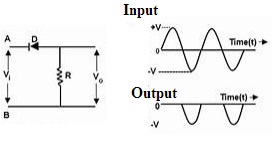
The positive cycle of the signal is clipped in the type of clipper. This circuit consists of a diode-connected in such a way that the arrow is pointing towards the input. It is connected along with series to the output load. The resistor is considered as load.
Series Positive Clippers
For the positive duration of the cycle, the connected diode will be reversely biased resulting in no current flow is evident. Hence the positive cycle is eliminated from the circuit. But when the negative cycle is supplied the diode-connected is maintained in forwarding bias mode. This results in the flow of the negative cycle of the diode.
Series Positive Clippers with Negative Reference
series clipper is connected with a voltage of negative reference along with a resistor. For the positive duration of the cycle, the value of output generated at the resistor is basing on the negative value of the reference voltage. For the negative duration of the cycle, the amount of output is generated if the voltage is greater than the ‘negative reference’.
Further, if the positive reference of voltage is connected along with the resistor then the positive duration of the cycle makes the circuit to generate the output as the reference voltage. For the negative duration of the cycle, the exact signal of input is generated at the resistor.
Series Negative Clippers
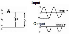
When the positive duration of the cycle is applied the diode will be in forward bias and the positive cycle of the signal is allowed to pass. During the negative duration of the cycle, the signal is blocked as the diode remains reverse biased. As the negative part of the signal is clipped it is known as a negative clipper.
Series Negative Clippers
Series Negative Clipper with the Positive Reference
In this type of circuit, a positive reference voltage is an additional component present along with a resistor. For the positive duration of the cycle, the diode tends to conduct due to the voltage at the anode exceeds the voltage value at the cathode. Hence the voltage at the cathode becomes equal to the voltage of reference and output has appeared at the resistor.
If the same circuit is applied with a value of negative reference so that the voltage at the cathode of the diode will be a negative one. So, for the positive duration, the complete positive cycle has appeared as it is at the output but for the negative duration, the input can appear at the output until the value of the input is lesser than the negative voltage of reference.
Shunt Clippers
In this type of circuit, the diode should be connected to the load in a parallel manner. The principle of operating is the opposite of the series clippers.
Shunt Positive Clippers
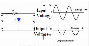
This type of clipper allows the applied input signal to pass to the load when the diode remains to reverse biased and the signals are blocked when the diode gets forward biased.
Shunt Positive Clippers
Shunt Positive Clippers with Positive Bias
For the positive duration of the cycle, the diode tends to conduct and the output has appeared as the positive value of reference voltage and for the negative cycle, the value of output generated is the same as that of the applied input signal.
Shunt Positive Clippers with Negative Bias
The positive duration of the cycle basing on the negative voltage of reference connected in terms of series along the diode will be the output. But for the negative cycle, the connected diode will conduct until the value of the input voltage will be greater than the value of the negative voltage of reference.
Shunt Negative Clippers
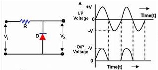
For the positive duration of the cycle, the exact input signal can be obtained as the output and for the negative duration of the cycle, there is no output generated.
Shunt Negative Clippers
Shunt Negative Clipper with Positive Bias
A positive voltage of reference is connected to the diode in series. For the positive cycle, the value of output can be generated as the applied input but for the negative duration of the cycle, the positive value of the reference will be generated as the output.
Shunt Negative Clipper with Negative Bias
The functionality of the circuit is the same but the only difference is a negative voltage of reference is connected in terms of series to the diode.
Clamper Circuit
The clampers are also known as DC Restorers. Basing on the amount that is defined by the voltage source the applied input signal can be shifted.
Working of Clamper Circuit
A clamper circuit consists of an independent voltage source, a resistor, a capacitor, and a diode. The capacitors and the resistors present in the circuit maintains the DC level altered at the output obtained. If the positive component of dc is added to the input signal then the signal gets pushed towards the positive side. similarly, if the negative component of dc is added the signal gets shifted towards the negative side.
Please refer to this link to know more about Clipper Circuit MCQs
Please refer to this link to know more about Clamper Circuit MCQs
Types of Clampers
Clamper circuits are of three types. They are positive, negative, and biased clampers.
Positive Clampers
A positive clamper has the source of voltage, resistor, capacitor, and a diode-connected parallel with the load. If the diode follows the reverse biasing mode the applied input signal is passed on to the load otherwise the signal gets blocked if the diode remains in forward biasing mode. In the positive clampers for the positive duration of the cycle, the connected diode is reverse biased and for the negative duration of the cycle, the connected diode will be forward biased.
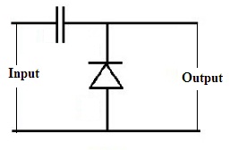
Positive Clamper
Negative Clampers
The circuit of negative clampers is arranged in such a way that for the positive duration of the cycle the polarity of the diode makes it to be in forward biased and for the negative duration, it will be reverse-biased so that the signal can appear at the output.
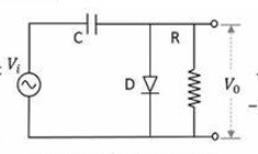
Negative Clamper
Applications of Clippers and Clampers
The applications of clippers are:
- To generate and shape the waveforms, clippers are used.
- Power supply units consist of clipping circuits.
- FM transmitters to remove the excess amount of ripples clipping circuits are used.
- To protect the transistors from the transients the diodes are connected in a parallel manner with the load that is inductive by nature.
The applications of clampers are:
- To remove the distortions and to identify the polarity of circuits the clampers are used.
- To improve the ‘Reverse Recovery Time’ clamping circuits are used.
- To mold the waveforms to the desired shape and the ranges clampers are used.
- SONAR systems and the testing equipment consists of clamping circuits.
Please refer to this link to know more about Clamper Circuit MCQs.
Thus, this is all about an overview of clippers and clampers circuits. These circuits are used to shape the signals into desired forms. These circuits are simple in terms of design by using basic diodes. A clipping circuit consists of a diode followed by a resistor whereas an additional component called a capacitor is present in clampers. Can you describe the other way of construction of clippers and clampers other than diodes?