We all know that an operational amplifier is the analog type of circuit that considers differential voltage as input and provides a single-ended voltage as output. These op-amps are mainly employed in the voltage follower circuits. But the arrangement of the op-amp in the voltage follower imposes high risk and capacitive stacking of oscillations. These huge loads show more impact on the operational amplifier stability dependent applications. So, let us know how the arrangement can be done in a simpler way and also what is a voltage follower, how it works, and other considerations.
What is a Voltage Follower?
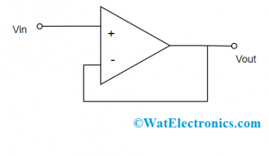
There are many other names for a voltage follower circuit which are isolation amplifier, unity-gain amplifier, and buffer amplifier. It is an operational amplifier circuit where the output and input voltages are equal. Because of this, a voltage follower op-amp will not amplify the input signal but has a gain of one. It provides only buffering but no amplification to the circuit and has a high level of impedance. With these features, the circuit opts for various kinds of applications that need isolation in between input and output signals. A basic voltage follower circuit is shown as follows:

Voltage Follower Circuit
As the circuit has unity gain, this is attained through negative feedback connection which means that the input signal is connected to the op-amp’s non-inverting input terminal and the output is applied directly to the input’s inverting terminal.
When the op-amp functions like an open-loop amplifier which means without having a negative feedback connection, there is a minimal rise in the input voltage which leads to more increase in the output voltage level as because op-amp has increased gain.
With the negative feedback in the voltage follower, it generates a compensating effect which makes the increased output voltage value to deliver across the negative terminal of the differential input section, and correspondingly there is a decrease in the output voltage. The final impact of negative feedback in this circuit is to trigger the output voltage to be equal to the input voltage valve at the non-inverting input end.
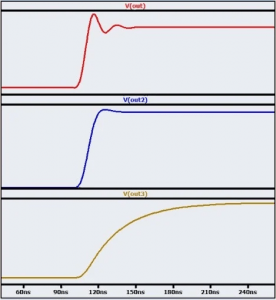
Whereas when the input signal show deviations which are minimally relative to the operational amplifier’s dynamic ability then there will be no setting actions. Here, one can observe directly that signal and input signals are equal. Though, the settling activity is clear when there is an application of quick transition to the voltage follower circuit. The below graph depicts the setting behavior of the circuit.
What is the Purpose of a Voltage Follower?
In general, a voltage follower circuit does not either increase or decrease the input signal’s amplitude level and even it does not filter high-level frequency noises. With this one might be in the thought that does this kind of circuit is useful in any application.
Let us now know the detailed scenario behind the purpose of voltage follower and how it is arranged to suit various applications.
As discussed, that voltage follower circuit does not directly change the input signal’s amplitude or frequency characteristics whereas it permits to increase of the impedance connections. When there is the transmission of the voltage signal from one sub-circuit to another, the output impedance of the source and the input impedance of the load sub-circuits have to be considered. This forms a voltage divider and correspondingly the voltage transfer level is based on the proportion of input and output impedance values. For effective voltage transfer, there is a need for a source circuit having minimal output impedance and a load circuit having high input impedance values.
This kind of arrangement is simple and suitable to solve complicated impedance relationships. When there happens signal transfer from high-output impedance sub-circuit to low-input impedance sub-circuit, then the voltage follower that is in between these sub-circuits makes sure that there is the complete transfer of voltage to the load section.
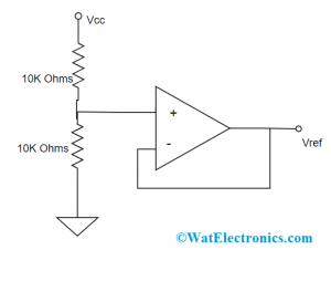
Consider a simple voltage-follower circuit as shown in the below diagram.

Application of Voltage Follower
Here, a resistive voltage divider delivers reference voltage VREF, however, the output impedance is not minimal mainly when the high-value resistors are employed in the approach of decreasing current utilization. This arrangement is not negatively impacted by the voltage divider’s output impedance and generates minimal output impedance to be used for other elements that are present in the circuit.
Stability
It is known that everyone uses a voltage follower circuit to generate an output signal following the input signal. But the problem to consider here is the circuit’s stability. Because the device is easily vulnerable to oscillations and this shows an impact on the voltage follower stability.
Oscillations in the negative feedback connected amplifiers are correspondent to the phase shift where this triggers negative feedback to turn into positive feedback. It might be thought that voltage follower will not have any kind of stability issues because the device will not do any amplification. But these circuits are easily reactive towards oscillations than any other circuits having higher gain values
In many of the scenarios, it is needed to eliminate oscillation in the circuits and the operational amplifier is selected that has unit gain stability. These operational amplifiers are internally compensated in the way that they generate a frequency response which permits for good stability even when the machine is utilized in any of the voltage-follower configured devices.
Gain
The gain of voltage follower is one where because the name itself and the functionality states that output voltage is followed with the input voltage. Even though the gain of the voltage buffer amplifier is nearly one, it generates significant power gain and current. Regardless of this, it is more general than the device has the gain of ‘1’ corresponding to voltage gain.
Voltage Follower in Voltage Divider Circuits
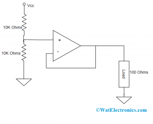
In the electrical circuits, it is the common scenario that voltage is either delivered or shared with the resistance or impedance of the connected elements. When an operational amplifier is connected, there will be a huge voltage drop because of its high-level of impedance. So, when a voltage follower is implemented in the voltage divider circuits, it allows for the supply of necessary voltage to the load. The below diagram shows the connection of voltage followers in voltage divider circuits.
Here, a voltage divider is placed in between the two 10KΩ valued resistors and an op-amp. Here, the operational amplifier will provide input resistance in the range of MΩ. Let us consider that op-amp provides resistance of 100 MΩ. Them the equivalent parallel resistance value is 10KΩ || 100KΩ.
The voltage follower’s equivalent parallel resistance equation is
(10KΩ * 100KΩ) / (10KΩ + 100KΩ) = 9999Ω = 10KΩ
As per the above value, it is known that a voltage divider that has the same value of resistance will provide precisely half the value of the power source voltage. This can be proved through the voltage divider equation which is given by
VOUT = VIN * (R2)/(R1 + R2)
= 10V * (10KΩ)/(10KΩ + 10KΩ) = 5V
So, there will a drop of 5V across the 10KΩ resistances those are at the top and bottom places and the load resistance which is of 100Ω as because 10KΩ || 100KΩ, the same level of voltage will drop in the resistors those are in parallel to this. As we know that an operational amplifier operates as a buffer to provide the required level of voltage for load connection. In a similar circuit without having the voltage follower, it will not function because of the unavailability of the required voltage level across the load section.

Divider Circuit
Mostly, a voltage follower is used in the circuits for two crucial reasons where one is for isolation and the other reason is for buffering the output voltage from the electric circuit to gain a selected level of voltage to the load which is connected.
Advantages of Voltage Follower
The advantages of voltage follower circuit are:
- The device delivers a gain of both current and power
- The minimal output impedance of the circuit makes use of the output
- It utilizes ‘0’ current from the input section
- No loading effects are there
- There will be no amplification in the input signal
- Minimal output impedance
- Transmission gain is unity
Applications
The applications of voltage follower circuit are:
- Used in buffers for the logic circuits
- Employed in S & H circuits
- Used in active filters
- Utilized in bridge circuits through the transducer
Please refer to this link to know more about Stack and Stack Pointer.
This is the voltage follower circuit explanation. The article has provided a clear and elucidated explanation of the voltage follower circuit, equation, its usage purpose, advantages, and applications. Furthermore, know what are the examples of voltage followers and their importance too?
