In most electronic circuits, the Zener diode can be used as a voltage regulator to give a precision voltage reference. Thus, TL431 IC almost performs like a Zener diode apart from the voltage rating of this chip is programmable. This IC was introduced by Texas Instruments in 1977 but the original IC remains in production with a huge number of clones & derivatives in the 21st century like; TLV431, ATL431, TL432, KA431, TS431, LM431, 142ЕН19, etc. These ICs have the same functionality but differ in layout, die size, speed characteristics, precision safe operating areas, minimal operating currents, and specific voltage reference. This article discusses an overview of TL431 IC, pinout, features, specifications & its applications.
What is TL431 IC?
The TL431 is a three-terminal adjustable shunt voltage regulator IC that regulates voltages from 2.496 to 36 V and up to 100 mA current with an external voltage divider. The typical primary reference voltage deviation from the nominal 2.495V level can be measured in mV. This IC can be programmable easily with an external voltage divider and provides a stable reference voltage to the remaining components within the circuit. These ICs have 0.2Ω typical dynamic output impedance which are excellent replacement for Zener diodes within various applications.
TL431 IC Pin Configuration:
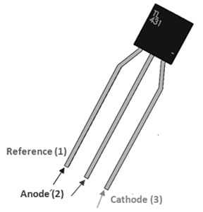
TL431 IC pin configuration is shown below. This IC includes three pins which are explained below.

TL431 IC Pin Configuration
- Pin-1 (Reference): This reference pin sets the voltage rating for the TL431 IC.
- Pin-2 (Anode): This terminal allows the flow of current.
- Pin-3 (Cathode): Current flow exits always throughout this terminal.
Features & Specifications:
The features and specifications of TL431 IC include the following.
- TL431 IC is an adjustable and precise shunt voltage regulator.
- This IC includes three pins and is available in SO-8, TO-92 & TO-220 packages.
- Its programmable o/p voltage is upto 36 Volts.
- Its voltage reference tolerance typically is ±0.4% at 25°Centigrade.
- Typical low dynamic o/p impedance is 0.22 Ω.
- Sink current capability ranges from 1.0 mA – 100 mA.
- Its typical equivalent full-range temperature coefficient is 50 ppm/°C.
- It has less output noise voltage.
- It is AEC−Q100 qualified & PPAP capable.
- This IC is Halogen Free, Pb−Free, BFR Free & are RoHS compliant.
- The output voltage of this IC can be set to voltage value which ranges from 2.5 to 36 volts with two external resistors.
- This IC has guaranteed thermal stability above applicable temperature ranges.
- It handles up to 100 mA output current.
- It has 0.2 Ω typical dynamic output impedance.
- This IC acts as a voltage comparator to contrast the reference voltage with the input voltage.
- It has a stable voltage source below a variety of conditions due to it being resistant to fluctuations & disturbances within the voltage supply.
TL431 IC Internal Circuit
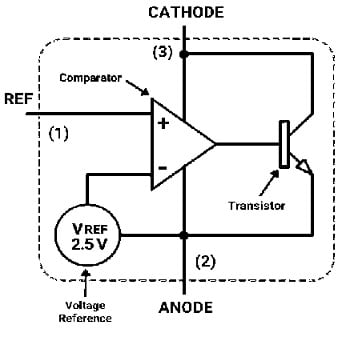
The TL431 internal circuit diagram is shown below which includes three significant components like the following.

TL431 IC Internal Circuit
Reference Voltage Source or VREF
The TL431 IC has a voltage reference source internally that provides a constant and accurate 2.5 V reference voltage, So this reference voltage is the main voltage that the regulator struggles to keep at its o/p terminal.
Comparator
The comparator compares the i/p reference voltage from the exterior voltage divider circuit to the voltage reference. So the input voltage can be connected simply to the non-inverting terminal of the comparator whereas the VREF can be connected to the inverting terminal. So this comparator monitors the input voltage continuously and adjusts the o/p accordingly.
Transistor
An NPN-type transistor is utilized to control the flow of current toward the connected load. Whenever the input reference voltage goes beyond the voltage reference, the comparator produces a control signal to control the transistor. So this transistor either lets current supply toward the load based on the voltage variation between the VREF and input reference. So this action guarantees that the output voltage remains constant and matches closely the reference voltage.
Working Principle
The TL431 is a voltage regulator IC that works by comparing the i/p voltage with an internal reference voltage. If the input voltage is below the reference voltage, then the transistor will be turned off then the output will be logic high. Similarly, if the input voltage is higher as compared to the reference voltage, then the transistor will be turned ON then the output will be logic low.
This adjustable shunt voltage regulator is set up with an exterior voltage divider to adjust voltage, thus it regulates voltages from the range of 2.495 to 36 V. So this IC be used in different applications like; switching power supplies, on-board regulation & adjustable power supplies.
Equivalents & Alternatives
Equivalent TL431 ICs are; TL431LI-Q1, TL432LI-Q1, SCV431AI, NCV431AI, TL431AC, TL431BI, TL431BV, TL431BC, etc. Other Voltage regulator ICs are;TLV43, TL432, ATL431, KA431, LM431, TS431, 142ЕН19, etc.
Voltage Drop Alarm Circuit with TL431 IC
This simple voltage drop alarm circuit is very helpful in monitoring (or) testing the power supply. It is also required sometimes to observe the voltage & take proper action whenever the voltage falls under a set level. This circuit generates an audible alarm sound whenever the voltage falls otherwise the power source falls short. This circuit keeps the connected buzzer active even after the voltage comes back to its normal stage. So the buzzer will stay active until the reset button is pushed.
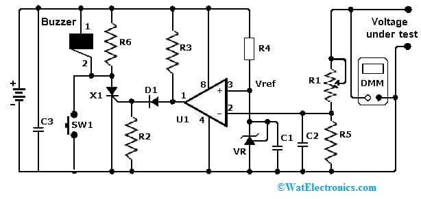
The required components to make this voltage drop alarm circuit mainly include; LM393 IC, TL431, 2N5060 Thyristor, 1N5060 Diode, 1N4148 Diode, 1 47K potentiometer, resistors like; 1 10K, 1 2.2K, 1 6.8K, 1 4.7K, 1 1K, capacitors like 0.01 uF and 0.1 uF, buzzer and NO switch. Connect this circuit as per the diagram shown below.

Voltage Drop Alarm Circuit
Working
The voltage drop alarm circuit uses the LM393 IC with a 2.5 V programmable voltage reference on its non-inverting terminal. This shunt regulator IC provides the voltage reference. This circuit works with a 9V battery (or) an external power source.
The comparator in the circuit compares the voltage reference with the voltage source output by separating the voltage with the R1 potentiometer and R5 resistor. Here R1 Potentiometer is mainly utilized to regulate the voltage under test.
Whenever the test voltage falls below the reference voltage, the output of the comparator goes from lower to higher by triggering the thyristor then it turns on the buzzer to generate sound. When the switch SW1 is pressed momentarily then the buzzer remains active. The R6 resistor in parallel through the buzzer guarantees that the flow current throughout the SCR turns ON the buzzer even when the output of the comparator goes low.
Here, a digital voltmeter measures the voltage across the R5 resistor until it attains the preferred level over the reference voltage. After that, the digital multimeter can be connected in parallel with the test voltage mainly for a visual display. Once the test voltage falls under the reference voltage, the alarm must sound.
Advantages & Disadvantages
The advantages of TL431 IC include the following.
- The TL431 IC has an adjustable output.
- It is protected from voltage supply fluctuations & disturbances to make it a stable voltage source.
- It is a low-cost IC and is available in small sizes.
- This IC acts as a voltage comparator.
- It is available in various packages like; TO-92, SO-8 & TO-220.
- This IC can replace Zener diodes within many applications like adjustable power supplies, onboard regulation & switching power supplies.
The disadvantages of TL431 IC include the following.
- It is unstable.
- This IC has limited open-loop gain.
- Its maximum ratings may cause permanent damage to the circuit.
- Operating this IC at the absolute highest TJ of 150°C affects reliability.
Applications
The applications of TL431 IC include the following.
- The TL431 IC can be used frequently as a window voltage detector, Undervoltage monitor, voltage comparator, overvoltage monitor, etc.
- This IC can be used within an overvoltage protection circuit to shut down equipment automatically whenever its power crosses a set voltage value.
- TL431 regulator is used in SMPS, isolated power supplies, voltage comparators with integrated reference, current regulation circuits, precision reference voltage source circuits, etc.
- It is used in regulated power supply circuits, overvoltage protection circuits, voltage monitors, constant current source circuits, controllable shunt characteristics, etc.
- It is used where Zener diode replacement is necessary and also in solar applications.
- This IC is used in battery chargers and monitor circuits.
- This IC is used as a shunt regulator, series pass regulator, TRIAC crowbar, SRC crowbar, linear ohmmeter, voltage monitor, high efficiency based step−down switching converter, high current shunt regulator, simple 400 mW phono amplifier, etc.
Please refer to this link for the TL431 IC Datasheet.
Thus, this is an overview of TL431 IC, pinout, features, specifications, circuit, working and pros, cons, and its applications. Here is a question for you, what is TS431 IC?