The thermocouple was first designed after the examination of the thermoelectric phenomenon in the year 1821 by Thomas Johann Seebeck. He observed a circuit that contains two wires made with two different metals like platinum or bismuth & antimony which are connected jointly at their ends. So heating one of the junctions will produce a weak electric signal that is simply proportional to the variation in temperature among the two welds. So this type of arrangement is known as a thermocouple. If the circuit contains different metal pairs which are connected together, then this arrangement is called a thermopile. So this device was invented by Leopoldo Nobili from 1784 to 1835 & Macedonio Melloni from 1798 to 1854. This article discusses an overview of a thermopile – construction, working, benefits with applications.
What is Thermopile/Thermopile Definition?
A thermopile can be defined as; an electronic device that changes the energy from thermal to electrical energy. Thermopiles include various thermocouples which are connected normally in series but less commonly connected in parallel. The thermopile diagram is shown below.
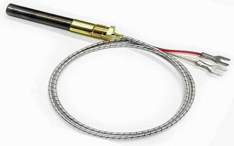
Thermopile
Thermopile Construction
The structure of the thermopile is shown below. The output voltage of a single thermoelectric cell is extremely small. So a number of these cells is connected in series/parallel to get a larger signal output. The arrangement of this thermocouple stack is called “thermopile”.
To make a thermopile, we need to connect more thermocouple pairs in series, so that it increases the output voltage. Thermopiles are designed with a set of thermocouples which includes dual thermocouple junctions otherwise various thermocouple pairs. A thermopile includes a series of thermocouples where each includes two special materials with large thermoelectric power & reverse polarities which are interconnected in series.
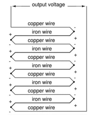
Thermopile Structure
These thermocouples are arranged throughout the cold & hot areas of the arrangement where the hot junctions are isolated thermally from the cold junctions. In reply to the temperature variation across the material, the output voltage of the thermopile is called a Seebeck coefficient or thermoelectric coefficient. So it is measured per kelvin (V/K) otherwise mV/K in volts.
Thermopile sensors utilize infrared radiation to transfer heat and are also utilized for measuring non-contact temperature. As a result, it is used within industrial pyrometers, IR thermometers, temperature control in moving objects, life care instruments, etc.
Thermopile Connections
The thermopile connection includes multiple thermocouples which are connected either in series or parallel to get maximum output signal. So when the output voltage is more then we can measure the temperature of an object more precisely.
Thermopile Connections
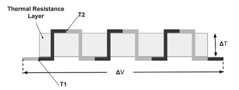
In the above connection diagam, thermocouples are connected in a chain model. At ‘T1’ temperature, the two peak thermocouples are connected junctions, while the two underneath thermocouple junctions are at T2 temperature.
The output voltage from the ΔV thermopile is proportional directly to the difference in temperature (T1-T2) across the layer of thermal resistance & the no. of thermocouple junction pairs.
The formula for calculating output voltage is given below.
The o/p voltage of the thermocouple = S x difference in temperature.
The o/p voltage of thermopile = S x N x difference in temperature.
From the above formulas, ‘S’ is a Seebeck co-efficient and ‘N’ is no. of thermocouples.
Thermopile Working Principle
Thermopile works on the thermoelectric effect principle which means that, it generates a voltage when different metals like thermocouples are exposed to a difference in temperature. These metals simply work by determining the temperature difference from the point of their junction to the point where the thermocouple o/p voltage is calculated.
Whenever a closed circuit is designed with above one metal & there is a variation within temperature in between junctions as well as points of transition from one metal to another metal, then current is generated like a potential difference generated between the cold & hot junction.
Thermocouples are arranged in series like the pairs of thermocouples with a junction arranged on any side of a thermal resistance layer. So, the output from this pair is a voltage that is directly proportional to the difference in temperature across the layer of thermal resistance & also to the heat flux throughout the thermal resistance layer. When more thermocouple pairs are connected in series then it increases the o/p voltage’s magnitude.
Thermopile Vs Thermocouple
The difference between thermopile and thermocouple includes the following.
|
Thermopile |
Thermocouple |
| An electronic device that is used to change the energy from thermal to electrical is called a thermopile.
|
A thermoelectric instrument that is used to measure temperature is known as a thermocouple. |
| The size of the thermopile is thicker. | The size of the thermopile is thinner. |
| The thermopile temperature range is from 25°C to +100 °C. | The temperature detection range of the thermocouple is -200° to 350°C. |
| It is helpful in measuring the non-contact-based temperature | It is helpful in measuring contact-based temperature. |
| It is designed to combine thermocouples which are simply connected in series/parallel connection. | It is designed by using two kinds of wires with different materials. On the first wire, heat lies & moves to reach the next wire. Once it reconnects, then these wires generate electricity. |
Difference between Bolometer and Thermopile
The difference between a bolometer and a thermopile includes the following.
| Bolometer |
Thermopile |
| A bolometer is a sensitive device that is used to detect & measure electromagnetic radiation energy. | Thermopile is an electronic device used to change thermal energy to electrical energy. |
| The Bolometer is designed in a bridge circuit form and it includes a resistive element that is responsive to temperature. So, this element detects & measures the power of specified input microwave energy. | It is designed with thermocouples that are connected in series combination. |
| The bolometer works with the thermo-resistive effect. | This device simply applies the Seebeck/ thermoelectric effect to implement a transducer that depends on temperature. |
| The response time of the bolometer is 10ms. | The response time of the bolometer is 20 to 50ms. |
How to Choose a Thermopile?
The type of metal is a significant consideration when choosing thermopiles. So, the thermopiles with base metal can measure a different range of temperatures based on the material type of sensor. Every type or designation signifies a specific type of metal & range of temperature.
- The temperature range of Type-E (chromel/constantan) ranges from -270° C to 1000° C.
- The temperature range of Type-J (iron/constantan) ranges from -210° C to 1200° C.
- The temperature range of Type-K (chromel/alumel) ranges from -270° C to 1372° C.
- The temperature range of Type-N (nicrosil/nisil) ranges from -270° C to 1300° C.
- The temperature range of Type-T (copper/constantan) ranges from -270° to 400° C.
- The temperature range of Type-B (noble and refractory metals) temperature ranges from 0° C to 1820° C.
- The temperature range of Type-S (platinum 10%/ rhodium) temperature ranges from -50° C to 1768° C.
- The temperature range of Type-R (platinum 13%/rhodium) temperature ranges from -50° C to 1768° C.
- The temperature range of Type-W (tungsten/rhenium) temperature ranges from 0° C to 2300° C.
Thermopile Arduino
The TMP007 is an infrared thermopile sensor from Texas Instruments that is used to measure an object’s temperature without making contact with the object. The thermopile which is integrated will absorb the IR energy produced by the object within the sensor field of view. The interfacing of a thermopile with an Arduino is shown below.
In this interfacing, we can see synchronous serial communication with the I2C protocol. In order to read the object’s temperature in front of the sensor, you will communicate by an IR temperature sensor chip using a microcontroller.
The required components for this interfacing mainly include an Arduino board, TMP007 thermopile sensor, breadboard, and connecting wires.
TMP007 Thermopile Sensor Pinout
The TMP007 Thermopile Sensor includes two power pins like VCC, GND, and I2C Data Pins like SCL, SDA, and Optional Pins like ALET, AD0 – AD1.
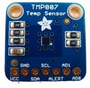
TMP007 Thermopile Sensor Pinout
VCC: This is the +Ve power & logic level pin which uses 2.2 to 5.5VDC.
GND: This is the GND power & logic reference pin.
SCL: This is the I2C CLK pin.
SDA: This is the I2C data pin.
ALET: This is the alert/ interrupt pin of the sensor. This IC has some capacity to give alert you if the IC temperature goes below or above a set amount. So, this o/p can activate to allow you to know.
AD0 to AD1: These pins are the address select pins. As you can have a single device only with a specified address on an I2C bus, there should be a method to regulate the address if you desire to put above one TMP on a shared I2C bus. These pins set the base 3- pins of the i2c address.
Give the connections as per the following interface diagram. Connect the TMP007 thermopile’s VCC & GND connections to the Arduino’s VCC & GND pins. For clock & serial data connections, we need to connect the I2C data pins of the sensor to Arduino like the SCL pin of the sensor to the A4/SDA pin of Arduino and the ALET pin of the sensor to the A5/SCl.
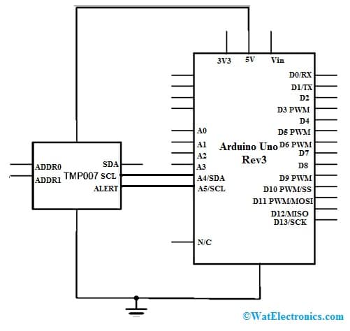
TMP007 Interfacing with Arduino
Once the connections are made, we need to upload a program to control it. The main benefit of the I2C synchronous serial protocol is that you always require two wires for communication to a single or many devices.
Code
#include “Wire.h”
#include “Adafruit_TMP007.h”
Adafruit_TMP007 tmp007; // instance of the sensor library
void setup() {
Serial.begin(9600);
boolean sensorInitialized = tmp007.begin(); // initialize the sensor
while (!sensorInitialized) {
// Do nothing until sensor responds
Serial.println(“Sensor is not responding”);
}
}
void loop() {
if (millis() % 4000 < 2) { // if 4 seconds have passed
float objectTemp = tmp007.readObjTempC(); // read object temperature
float chipTemp = tmp007.readDieTempC(); // read chip temperature
// print the results:
Serial.print(“Chip temperature: “);
Serial.print(chipTemp);
Serial.print(” deg. C. \t Object temperature: “);
Serial.print(objectTemp);
Serial.println(” deg. C”);
}
}
I2C protocol is a commonly used protocol along with several ICs & it is handy because you can merge several devices on a similar bus. But you need to check the addresses of a device are unique. Every device will have its own method to modify the address. So for the TMP007 sensor, you must set the address pins like AD1 & AD0 on the breakout board properly to modify the address.
Advantages and Disadvantages
The thermopile advantages include the following.
- It doesn’t need an external power supply.
- It gives a stable response to DC radiation which is gone from temperature-measuring bodies.
- It has stable response characteristics.
- Thermopile is a non-contact temperature-detecting device that uses IR radiation to transfer heat.
- These are available in small sizes.
- It is less costly.
- It generates larger o/p voltage because of the usage of several thermocouple devices.
The thermopile disadvantages include the following.
- These are static, so not used ones should be stored within conductive material to defend them from static discharges & static fields.
- These can be damaged due to stress and reverse the polarity of the supply.
- These should not be directly exposed to moisture or sunlight because this may harm or will have corrosion on the device’s performance.
- These devices need maintenance.
- This device should not be operated with dirty or oily fingers because this dust will affect the device’s performance. For superior performance, we need to clean with cotton swabs or alcohol.
- For precise temperature measurement, an object should fill the field of view completely of the thermopile device.
Applications of Thermopiles
The applications of thermopile include the following.
- Thermopiles are mainly used to measure non-contact temperature.
- These are very helpful in measuring temperature within consumer electronics like mobile phones, microwave ovens, climate control of a car, etc.
- These can be used as temperature-detecting devices in IR thermometers.
- These are used to measure environmental temperature within HVAC systems.
- It monitors process temperature.
- It is used to measure noncontact temperature within process & industrial control-based applications.
- It is used to detect the refrigerant leak.
- These are used to monitor blood glucose.
- These are used in controlling light, thermal line scanners, control of automotive HVAC, sensing automotive occupancy, and analysis of exhaust gas in automotive-like CO2, HC & CO.
- It is used to analyze medical gas like incubator CO, CO2, Anesthetic, blood alcohol breathalyzers, etc.
- Used for hazard detection like explosion & flame.
- Detection of fire within transportation tunnels.
- Used to detect fire in aircraft.
This is about thermopile– construction, working, differences with bolometers, thermocouples, their advantages, disadvantages with applications. Thermopiles do not react to complete temperature but produce an o/p voltage which is proportional to a temperature gradient or limited temperature difference. To know about thermopile click Here .