A color sensor is an easy-to-use and simple sensor, used to recognize the object color to take appropriate action. This sensor detects the intensity of received light for blue, green and red respectively to make it possible to decide the object’s color. This sensor provides simple solutions for sorting & packaging within an industrial environment while costly sensors are utilized in industries. The examples of this sensor includes; TCS3200, AS73211, TCS3400, TCS34727, TCS34715, SEN-11195, Lego Mindstorms EV3, colorPAL from parallax, many more. Thus, this article provides an overview of the TCS3200 color sensor, its workings, interfacings, and applications.
What is the TCS3200 Color Sensor?
The TCS3200 is a color sensor that detects and measures various colors depending on their wavelength. This sensor module includes the TAOS TCS3200 RGB Sensor IC and is equipped with four white LEDs to light up the object, ensuring precise color detection. This sensor chip has an 8×8 Photodiode array to decide the color of an object exactly and generate a frequency signal equivalent to the detected color with a Current-to-frequency converter.
The TCS3200 module uses a CMOS IC with configurable silicon photodiodes & a current-to-frequency converter to generate a square wave output. So the output frequency is directly proportional to the intensity of light. Thus, the TCS3200 module is utilized in color recognition projects like color sorting, color matching, ambient light sensing, and test strip reading.
The detection range of the TCS3200 module is 100 mm and it operates with a single voltage supply that ranges from 2.7V to 5.5V. So it is well-matched with almost all common microcontrollers like; AVRs, PICs, Arduino, and ARM.
TCS3200 Color Sensor Working Principle
The TCS3200 color sensor works by noticing the color of an object with the photodiodes, filters & LEDs combination. So this sensor includes an array of 16 photodiodes including red, green & blue filters. So photodiodes in this sensor change light into current.
The filters in this sensor allow a specific color light to pass throughout to the photodiode under it. So the filter pattern is known as the Bayer pattern. The LEDs in this sensor light up a target object and light up it through modulated light.
This sensor gives a square wave output with a frequency that corresponds to the color & the light intensity. So the frequency is directly proportional to the intensity of light. The TCS3200 color sensor module is used in different applications like test strip reading, color matching, sorting by color, and ambient light sensing & calibration. Thus this module is not designed for critical applications where failure could result in death or injury.
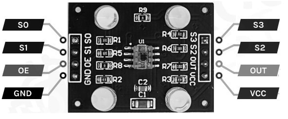
TCS3200 Color Sensor Pin Configuration:
The TCS3200 Color Sensor module includes 8 pins which are digital, apart from VCC & GND. So each pin and its functionality are discussed below.

TCS3200 Color Sensor Pin Configuration
- Pin (VCC): This is the power supply pin of the module that is connected to 3.3V or 5V of the supply.
- Pins (S0 & S1): These pins are used to choose the o/p frequency scaling percentage of the module. Once these pins are configured then it can be situated to 2%, 20% (or) 100% scaling.
- Pins (S2 & S3): These pins are used to choose the color array of the module. By choosing the correct color array continuously, thus this sensor recognizes a color.
- Pin (OE): This Output Enable (or) Disable pin of the sensor is pulled down on the module to disable the sensor by providing a higher pulse to OE pin.
- Pin (OUT): This is the o/p pin of the sensor module. Whenever a particular color is noticed through the sensor, then the output pulse frequency will be changed by noticing this change within pulse width we can decide the color.
- Pin (GND): This is the ground pin of the module and it must be connected to the GND pin of the Arduino board.
Features & Specifications:
The features and specifications of the TCS3200 color sensor include the following.
- TCS3200 is a high-quality light sensor that detects any color by merging red, green & blue colors.
- Its operating voltage ranges from 2.7 to 5.5 V.
- It is compatible with microcontrollers like PICs, Arduino, ARM & AVRs.
- Interface is digital frequency i/p & o/p.
- The minimum operating temperature is 70 °C.
- Output frequency ranges from 2 Hz to 500 kHz.
- The communication interface is S0-S3 E0 OUT.
- Pin specification is standard 100mil.
- The optimum distance to detect the object is approximately 1 cm.
- The temperature coefficient is stable at 200 ppm/°C
- The TCS3200 module includes four white LEDs that light up the object ahead of it.
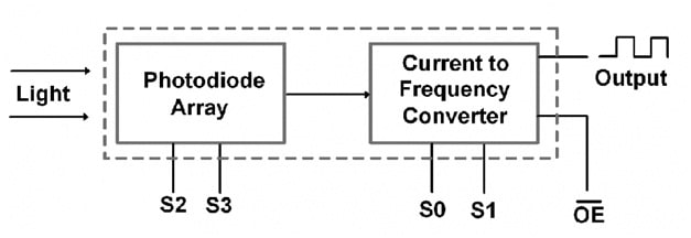
Block Diagram
The functional block diagram of the TCS3200 color sensor is shown below. So this block diagram includes a photodiode array and current-to-frequency converter.

Block Diagram
- As light from the target hits the photodiode array and each filter lets one color only pass through & blocks the remaining colors.
- After that, the current output of this photodiode array can be changed into frequency. So this output will be in the square waveform.
- When the input incident light changes then the current flow will be changed through the photodiode because of which the square wave frequency changes.
- Later the output square wave frequency is used to notice the color’s RGB content to describe the target’s color.
- Pins S2 & S3 of this module can be used to select an array of photodiodes like red, blue, green, and clear.
The frequency scaling can be selected with S0 and S1 pins.
Equivalents & Alternatives
Equivalent to the TCS3200 color sensor is TCS230. So alternative TCS3200 color sensors are; TCS34725, APDS-9301, TCS230, ISL29125 RGB light sensor, TSL2561 luminosity sensor, BH1745NUC color sensor, etc.
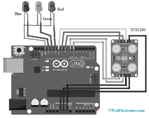
TCS3200 Color Sensor Interfacing with Arduino Board
The TCS3200 color sensor interfacing with the Arduino Board is shown below. So this interfacing is very simple using available components and connecting wires. For an indication of particular color detection, this interfacing uses three LEDs with an Arduino
The required components for Interfacing the CS3200 color sensor with the Arduino board mainly include; a TCS3200 color sensor module, Red, Blue, and Green 5mm LEDs, Arduino Uno R3, and Jumper wires. So the connections of this interfacing follow as;
TCS3200 color sensor’s VCC & GND pins are connected to the 5v & Ground pins of Arduino. In addition, OE must be connected to the GND.
The S0 to S3 and OUT pins of this sensor must be connected to the digital pins of the Arduino board.
The GND pins of common LEDs must be connected to the Arduino’s Ground pin while each LED’s +ve terminal is connected to separate digital pins on the Arduino board.

TCS3200 Color Sensor Interfacing with Arduino
Code
#define S0 6, S1 7, S2 8, S3 9, Out 10;
int redLed = 11, greenLed = 12, blueLed = 13;
void setup() {
Serial.begin(9600); // Change the baud rate to 9600
pinMode(S0, OUTPUT S1, OUTPUT S2, OUTPUT S3, OUTPUT);
pinMode(redLed, OUTPUT greenLed, OUTPUT blueLed, OUTPUT Out, INPUT_PULLUP); // Use INPUT_PULLUP to enable the internal pull-up resistor on the input pin
digitalWrite(S0, HIGH);
digitalWrite(S1, LOW); // Setting frequency selection to 20%
}
void loop() {
digitalWrite(S2, LOW);
digitalWrite(S3, LOW); // Setting for RED color sensor
int redFrequency = pulseIn(Out, LOW); // Reading frequency
Serial.print(“R: “);
Serial.print(redFrequency);
Serial.print(” “);
delay(500);
digitalWrite(S2, LOW);
digitalWrite(S3, HIGH); // Setting for BLUE color sensor
int blueFrequency = pulseIn(Out, LOW); // Reading frequency
Serial.print(“B: “);
Serial.print(blueFrequency);
Serial.print(” “);
delay(500);
digitalWrite(S2, HIGH);
digitalWrite(S3, HIGH); // Setting for GREEN color sensor
int greenFrequency = pulseIn(Out, LOW); // Reading frequency
Serial.print(“G: “);
Serial.print(greenFrequency);
//Serial.println();
if (redFrequency < blueFrequency && redFrequency < greenFrequency && redFrequency < 40) {
Serial.println(” – (Red Color)”);
digitalWrite(redLed, HIGH); // Turn RED LED ON
digitalWrite(greenLed, LOW);
digitalWrite(blueLed, LOW);
}
else if (blueFrequency < redFrequency && blueFrequency < greenFrequency && blueFrequency < 50) {
Serial.println(” – (Blue Color)”);
digitalWrite(redLed, LOW);
digitalWrite(greenLed, LOW);
digitalWrite(blueLed, HIGH); // Turn BLUE LED ON
}
else if (greenFrequency < redFrequency && greenFrequency < blueFrequency && greenFrequency < 85) {
Serial.println(” – (Green Color)”);
digitalWrite(redLed, LOW);
digitalWrite(greenLed, HIGH); // Turn GREEN LED ON
digitalWrite(blueLed, LOW);
}
else {
Serial.println(” – (NO Colour)”);
digitalWrite(redLed, LOW);
digitalWrite(greenLed, LOW);
digitalWrite(blueLed, LOW);
}
delay(500); // Add a delay before the next reading to reduce rapid changes
}
Working
The above code communicates with the color sensor using S0 to S3 & OUT pins.
So the LED output will specify the color quickly that has been noticed. Here frequency scaling is fixed at 20% thus we are putting the S0 and S1 pins as HIGH & LOW. Thus, controlling S2 & S3 pins in the loop commands the color sensor to notice all RGB frequencies frequently. So the OUT pin’s frequency value can be obtained by the PulseIn() function.
The IF conditions filter the o/p frequency to notice a particular color depending on the changes within the frequency
Thus the output frequency values of this sensor can be affected by the intensity of surrounding light & the color object ahead of it. But, it can also depend on the scaling factor.
The color object should be a material that reproduces some white light in the direction of the sensor.
This sensor calibration is a little complex but it can be done effortlessly. So, calibration in a stable surrounding light intensity can be done by fixing it at a permanent position.
So this code gives Serial monitor commands to adjust values on the serial monitor & changes can be made within the code.
Thus the above code is uploaded to the Arduino board and calibrates the color sensor correctly while not dislocating it. So calibration changes can be made in the code and properly tested 2 to 3 times.
The color-sensing device is Ready, so we place a red reflecting object ahead of the color sensor, and then the red LED will glow.
If we place the green color object, then the green color LED will glow.
Equally, the blue color object makes to glow Blue color LED.
Difference between TCS3200 and TCS230 Sensors
Both the TCS3200 and TCS230 color sensors are used commonly for color identification, detection and sorting, but there are some differences between them which include the following.
|
TCS3200 |
TCS230 |
| The TCS3200 color sensor detects a wide range of colors | The TCS230 color sensor detects a narrower range of colors with high precision. |
| These are not sensitive. | These are more sensitive, |
| This sensor includes an array of 8 x 8 photodiodes. | This sensor includes a smaller array of photodiodes. |
| This sensor is available in an 8-pin LCC package. | TCS230 sensor is available in a low-profile surface mount package. |
Advantages
The advantages of the TCS3200 color sensor include the following.
- TCS3200 color sensor has high-resolution conversion so this sensor optimizes the output range mainly for low-cost measurement methods.
- It reduces the required amount of board space when simplifying designs, thus it detects a wide range of colors.
- This sensor has separate digital o/ps for green, blue, and red channels, so it rejects IR from light sources.
- This sensor is well-matched with several microcontrollers, thus it can also be perfect for DIY electronics.
- This sensor helps in sorting objects depending on the color approach. So it helps in object counting.
- These are available at less cost which has driven its use within a lot of applications.
- Color sensor controller stores and can make color matching decisions with almost unlimited colors thus it uses advanced technology & memory loaded through color intensity data.
- It is simple to modify or change manufacturing setups without reprograming the color sensor. So this is helpful in low-volume manufacturing applications that have regular color variations.
Disadvantages
The disadvantages of the TCS3200 color sensor include the following.
- Its identification or color matching can be done in applications that require pass or fail output only.
- The operating distance range of these sensors is a matter of concern. So it needs to be selected suitably with exact testing within the setup.
- The fluctuations within lighting can affect the accuracy of its photodiodes.
- It is expensive, particularly for medium and small-sized businesses, so it generates large amounts of data that can be hard to process, analyze, and manage.
- They have a slow response time when light intensity changes.
- Its installation is complex.
- Its proper alignment is essential, which can enhance cost and installation time.
- This sensor might struggle with extremely transparent (or) shiny objects, so that can interfere with the reflected light.
- This sensor needs regular maintenance to keep the reflector very clean and ensure reliable performance.
Applications
The applications of the TCS3200 color sensor include the following.
- The TCS3200 sensor can detect & measure a wide range of colors depending on their wavelength.
So it is utilized to sort items through color. - This sensor reads test strips, thus it can be utilized for sensing and calibration of ambient light.
- This sensor can be used for identification and detection of color in industrial applications like paint mixing, robotics & food processing.
- It can be utilized to detect material in a variety of industries like manufacturing, automotive, beverage, and food.
- It detects color marks on parts within manufacturing.
- This sensor is used in process control for printing, health fitness systems, measurement of light color temperature, color detection & sorting operations.
Please refer to this link for the TCS3200 Color Sensor Datasheet.
Thus, this is an overview of the TCS230 color sensor module which detects the static color of an object with an array of photodiodes & filters by changing light into current. So the output of this sensor is a square wave including frequency which is directly proportional to the intensity of incident light. This sensor is used for reading test strips, color sorting, sensing & calibration of ambient light, & color matching. Thus it can also be used in different applications like assisting visually impaired people with different tasks like colors identifying in the laundry. So, here is a question for you, what is the TSL2561 sensor?