Stepper motor drivers are small pin-compatible modules designed particularly to drive stepper motors capable of continuously rotating with precise position control without the need for a feedback system. The stepper motor drivers have built-in converters that offer multi-stage resolution and variable current control that allows control of stepper motors with simple step and direction inputs. These modules are usually the main carrier boards for various stepper driver ICs that provide low-level interfaces such as inputs to initiate each step directly. A quick way to control a stepper motor is to use a stepper motor driver (controller) TB6600. This article gives a brief description of the TB6600 stepper motor driver module.
What is the TB6600 Stepper Motor Driver Module?
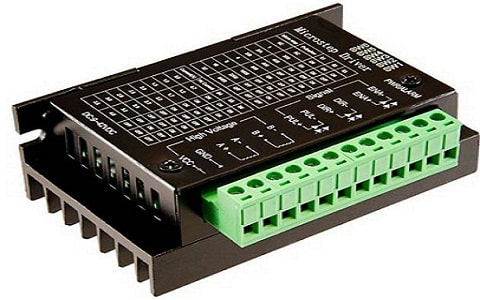
The TB6600 stepper motor driver IC is a very easy, effective, and professional device that can drive 2-phase stepper motors. Compatible with any type of microcontroller and Arduino to generate 5V digital output pulse signals. The TB6600 stepper motor driver has a wide input power range, (9-42VDC) of power supply, and generates 4 Amps peak current, supporting direction control and speed that is sufficient for most stepper motors.

TB6600 Stepper Motor Driver Module
The main benefit of using the TB6600 stepper motor driver IC is controlling the position and speed and is widely used for a small number of stepper motors. This type of driver allows you to minimize code and references. It is used in high-level applications. All the terminals of the driver provide the ability of anti-high frequency optocoupler isolation and can drive 2-phase stepper motors, 4-phase stepper motors, and hybrid stepper motors. Another benefit of using this driver is, it uses the bipolar H-bridge configuration for voltage and current control of the 2-phase and 4-phase stepper motors.
Features of TB6600 Stepper Motor Driver:
The following are the features of the TB6600 stepper motor driver.
- It is a Bipolar H-bridge DC driver.
- 8 output current types are optional up to 4 Amps. (0.5A to 3.5A)
- Divides up to 32 selectable 6 subdivision modes.
- Provides 8 kinds of micro steps (1, 2/A, 2/B, 4, 8, 16, 32).
- Provides high-speed photoelectric separation of the input signal.
- Full standard single pulse interface. > Offline hold function.
- Used in more harsh environments due to a semi-enclosed body.
- Provides a semi-automatic power lock function with energy saving.
TB6600 Pin Configuration/Pin Diagram
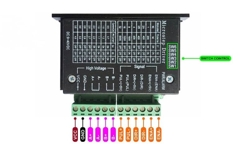
The TB6600 stepper motor driver module pin configuration/pin diagram is described below. There are 2 types of TB6600 driver modules such as 4A type and 4.5A type as shown below, with similar functions and pin configuration.

TB6600 Stepper Motor Driver 4A Module
- Pin 1: ENA- (ENA): This pin refers to the negative enable pin of the module.
- Pin 2: ENA+(+5V): This pin refers to the positive enable pin, which is the +5V pin of the module.
- Pin 3: DIR-(DIR): This pin refers to the negative direction of the motor.
- Pin 4: DIR+(+5V): This pin refers to the positive direction of +5V.
- Pin 5: PUL-(PUL): This pin refers to the negative pulse. (For controlling rotations steps of the motor)
- Pin 6: PUL+(+5V): This pin refers to the positive pulse of the motor.
- Pin 7: B-: This pin refers to the negative lead stepper motor coil wire 2.
- Pin 8: B+: This pin refers to the position lead of stepper motor coil wire 2.
- Pin 9: A-: This pin refers to the negative lead of stepper motor coil wire 1.
- Pin 10: A+: This pin refers to the positive lead stepper motor coil wire 1.
- Pin 11: GND: This pin refers to the common ground connection of the module.
- Pin 12: VCC: This pin refers to the input supply voltage for the stepper motor driver module, which is 9V-42V.
The in-built control/driver switches SW1, SW2, SW3, SW4, SW5, and SW6 are used to control the resolution of micro steps and used to limit the driver current. Switching of SW1, SW2, and SW3 changes the micro-step resolution from full step to 1/32 step.
Switching of dip switches SW4, SW5, and SW6 ON Or OFF adjusts current (0.7 to 4Amps) during the continuous motor run.
TB6600 Stepper Motor Driver Technical Specifications:
The technical specifications of the TB6600 stepper motor driver module are given below.
- The operating voltage ranges from 9-40V DC.
- The output current of the module is 0.7A-4.0A and it is selected in 8 steps through DIP switches
- The input pulse frequency is up to 20KHz.
- Input signal suitable for – 5V signal levels.
- Pulse per revolution is 200-6400.
- The logic signal current is 8A-15A.
- It is suitable for 2-phase and 4-phase stepper motors.
- It provides protection from overcurrent over-heat.
- Inputs are isolated optically.
- Insulation resistance is 500 megohms.
- It can support PUL/FIR mode.
- It is low cost.
Circuit Diagram in H-bridge Configuration:
The TB6600 stepper motor driver module is used to drive 2-phase and 4-phase stepper motors. It used a Bi-polar H-bridge configuration with MOSFETS. This type of driver module uses a step pin or direction pin to determine the direction of the stepper motor. That means, sending a pulse to the step pin causes the driver to change output, causing the motor to execute a step.
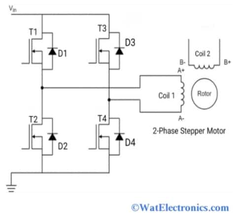
And the direction of the motor is determined by observing the direction pin level (High/Low). This driver is both current and voltage (change in steps) controlled. The circuit diagram of the 2-phase stepper motor in bipolar H-bridge configuration shown below helps to understand the working of the TB6600.

Circuit Diagram in H-bridge Configuration
From the above circuit, T1, T2, T3, and T4 are MOSFETs in the H-bridge configuration used to run the motor. The flyback diodes D1, D2, D3, and D4 are used to protect the motor from high voltages, and overcurrent and prevent damage. The leads of the 2 coils are A+, A-, B+, and B- used to control the direction of the rotation of the 2-phase stepper motor.
When the T1 and T4 are ON (active), the current flows from A+ to A- and the direction of the rotation of the motor is clockwise. When the T2 and T4 are ON, the current flows from A- to A- and generates the opposite magnetic field. It requires complex circuitry to achieve the maximum torque.
The TB6600 driver drives the 2-phase stepper motors in 4 modes to control the current flow and the step size. These modes are set by switching the in-built driver switches from SW1 to SW6.
Wave Mode:
In this mode, the current flows from the first coil leading A+ to A- (positive direction). That means, a single phase is energized with the generated magnetic field and the motor rotates in 90 degrees clockwise direction. Otherwise, the current flows in an opposite or negative direction. Similarly, the second phase B, and the process are continuous.
Full-step Mode:
In this mode, the 2 coils or 2 phases are energized at the same time with similar steps as in wave mode. Here, a strong magnetic field is generated and higher torque is produced.
Half-step Mode:
It combines both full-step and half-step modes. When both phases are energized, the step size is reduced by half (90 degrees to 45 degrees) and the produced torque fluctuates. When only one phase is energized, low torque is produced.
Microstep Mode:
It is the advanced mode of half-step mode used to reduce the step size and produce the constant torque. The current flow intensity in the phases of the motor can be controlled in this mode. But it requires a complex circuit.
How to use TB6600 with Arduino UNO?
The microcontroller or the Arduino can be used to control the speed, rotation direction, steps, or revolutions of the stepper motor. The TB6600 stepper motor driver module uses a bipolar H-bridge configuration and is operated in 3 modes such as wave mode, full-step mode, half-step mode, and micro-stepping mode. The microstrip resolution of the motor is set by using the control switches of the driver module. The TB6600 module is widely used in controlling the 2-phase stepper motors because it provides low voltage shutdown, overcurrent, and overheating protection.
This section explains how to use the TB6600 stepper motor driver module with the Arduino UNO. The components required are,
- Arduino UNO R3.
- TB6600 stepper motor driver 4A type.
- Stepper motor 1.65A.
- Battery for power supply.
- Jumper wires.
- Arduino IDE software.
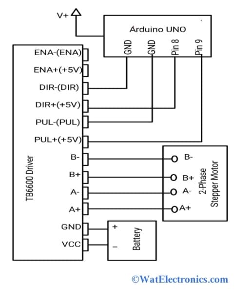
The interfacing diagram of the TB6600 stepper motor driver module is shown in the figure below.

Interfacing TB6600 With Arduino UNO
Make the connections as per the above diagram. Connections of TB6600 to Arduino, stepper motor, and battery are- DIR+(+5V) to Pin 8; PUL+(+5V) to pin 9; DIR-(DIR) and PUL-(PUL) to GND; A+, A-, B+, B- pins to the leads of the 2-phase stepper motor as shown in the diagram; VCC and GND to corresponding battery terminals. Upload the Arduino code and observe the rotation, speed, and steps of the 2-phase stepper motor.
Arduino Code:
#define dirPin 8
#define stepPin 9
void setup() {
// Declare pins as output:
pinMode(stepPin, OUTPUT);
pinMode(dirPin, OUTPUT);
// Set the spinning direction CW/CCW: (clockwise or counterclockwise)
digitalWrite(dirPin, HIGH);
}
void loop() {
// These four lines result in 1 step:
digitalWrite(stepPin, HIGH);
delayMicroseconds(500);
digitalWrite(stepPin, LOW);
delayMicroseconds(500);
}
When the DIR+(+5V) pin is set to high, the motor rotates in a clockwise (forward) direction and generates the square pulses with the step pin.
The microstrip resolution is changed by using the control switches SW1 and SW2. When SW1 is ON and SW2 is OFF, then micro step resolution becomes ¼ step. When SW1 is OFF and SW2 is ON, then it becomes ⅛ step. When SW1 and SW2 are OFF, then it becomes 1/32 step. When both switches are set, then it becomes a full step.
The following truth table shows the change in micro-step resolution.
| SW1 | SW2 |
Microstep Resolution |
|
OFF |
OFF | 1/32 step |
|
OFF |
ON | ⅛ step |
| ON | OFF |
¼ step |
| ON | ON |
Full Step |
To drive the stepper motor in an anticlockwise direction, then the TB6600 stepper motor driver 4.5A type module is used and the process is the same. Ensure that the current flowing in the motor should not exceed the peak current of the driver 4A. Use the control switches S4 and S6 to set the current flow.
Where to use/Applications?
The TB6600 stepper motor driver module applications are;
- Antennas.
- Setting the position of stepper motors.
- CNC (computer numerical control) machines
- 3D printers.
- High-level applications.
- Controlling speed, position, and direction of rotation of stepper motors.
- DSLR and Video Cameras.
- ATMs.
- Engraving machines.
know more about the Motor Driver and Microcontroller.
Please refer to this link to know more about the ULN2003 Motor Driver IC, L293D Motor Driver IC.
Please refer to this link to know more about the TB6600 Stepper Motor Driver Datasheet.
1. What voltage should I use with the TB6600 stepper motor driver module?
-The TB6600 stepper motor driver module can operate with a supply voltage of between 8-45V.
2. How do I control the speed of the stepper motor with the TB6600 driver?
-The TB6600 stepper motor driver uses pulse-width modulation (PWM) to control the motor’s speed. You can adjust the PWM frequency to change the speed of the motor.
3. Can the TB6600 driver handle high current stepper motors?
-The TB6600 driver can handle up to 4.5A of current, so it is suitable for stepper motors with a current rating of up to 4.5.
4. How do I change the direction of the stepper motor with the TB6600 driver?
-You can change the direction of the stepper motor by reversing the sequence of the input pins (IN1, IN2, IN3, and IN4). For example, if the sequence is IN1-IN2-IN3-IN4 for forward rotation, it will be IN4-IN3-IN2-IN1 for reverse rotation.
5. Can I use the TB6600 driver with a stepper motor with more than 4 wires?
-The TB6600 driver is designed for use with 4-wire stepper motors. If you have a stepper motor with more than 4 wires, you will need a different driver.
6. Can I use the TB6600 driver with a NEMA23 stepper motor?
-The TB6600 driver is suitable for use with NEMA17 stepper motor, however, it is not recommended for use with NEMA23 stepper motor due to its high current rating.
That about the TB6600 stepper motor driver module. It is a 4Amps 9~42V TTL 16 Microstep driver with 32 segments and an upgraded version of the Axis stepper motor with 42/57/86 segments. It is suitable for 42, 57, and 86-type stepper motors; and 4-phase, 2-phase stepper motors. The alternatives of TB6600 stepper motor driver modules are MKS-LV8729-OC, DRV8825, TB67S109, TMC2208, and A4988. Here is a question for you, what is a motor driver ?