The name of Schottky diode has come from the name of its inventor namely; Dr. Schottky, These types of diodes are metal-semiconductor devices designed with costly metals like silver, aluminum, gold, and platinum. Similarly, the SS series Schottky diodes are surface mount devices with low power loss and high efficiency. These diodes are available with clip-bonded leg structure which helps in providing less electrical resistance & high thermal performance. These SMD diodes are normally used in little current ESCs for immediate circuit rectification. This article provides brief information on the SS34 Schottky diode, pinout, specifications, circuit, and its applications.
What is the SS34 Schottky Diode?
SS34 Schottky diode is a surface-mount semiconductor diode with high-speed switching, low voltage drop, and high forward current. This diode can be formed with the metal and semiconductor junction and it has a guard ring arrangement across this junction to protect from stress. The SS34 SMD diode has a clip-bonded leg structure that provides low electrical resistance & high thermal performance. This diode has high surge current capability and high efficiency, so commonly used in secondary rectification, reverse polarity protection, freewheeling, and DC/DC converter applications. As compared to normal diodes, this kind of diode has a fairly faster switching speed, so it can be used within high-frequency switching circuits.
Pin Configuration:
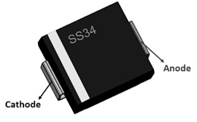
The pin configuration of the SS34 Schottky diode is shown below. This diode includes two terminals which are discussed below.

SS34 Pin Configuration
- Pin1 (Anode): This pin allows always the flow of current.
- Pin2 (Cathode): The flow of current exits always through this pin.
Features and Specifications:
The features and specifications of the SS34 Schottky diode include the following.
- SS34 is a power Schottky barrier diode.
- This diode has two terminals.
- It is available in different packages like; DO-214AA & SMC DO-214AB.
- Its manufacturer is ONSEMI
- Its forward current or IF is 3A.
- Its reverse current or IR is 0.5mA.
- Its maximum forward voltage (VF) is 0.5V at 3A.
- Its DC blocking voltage max is 40V
- Its reverse voltage max is 40V
- Its RMS voltage max is 28V
- Its forward drop of voltage is 22V.
- Its peak surge current is 100A
- Its operating temperature ranges from -65 to +150°C.
- It has a guard ring used for overvoltage protection.
- This diode has less power loss and high efficiency.
- It has less forward voltage drop.
- It has a high surge capacity.
- Its peak forward surge current is 100A.
- The rate of change of voltage (dV/dt) is 10,000V/μs
Equivalent & Alternatives
SS34 Schottky diode is an SMD equivalent of 1N5822 through-hole diode. Alternative SS34 schottky diodes are: SS33, SS32, 1N5822, and SS35 whereas other SS34 Schottky diodes are: 1N4733A, 1N4148 and 1N5824.
5V – 3.3V DC to DC Boost Converter Circuit with Xl6009 & SS34 Schottky Diode
Some components, electronic devices, microcontrollers, sensors, and ICs are designed to work on a 3.3V DC supply like a power source. When working with some projects using a typical 5-volt power supply or above, some circuits or modules would need lower 3.3V.
Here, the simplest voltage regulator circuit that can be used to reduce/step down the 5V or 9V available voltage supply to 3.3V. A 5volts to 3.3volts converter circuit is designed through various methods which include; using a boost converter, linear voltage regulator, zener regulator, resistor or voltage divider, switching converter, and many more. Here 5v to 3.3 v dc to dc boost converter circuit is designed with an Xl6009 linear power converter.
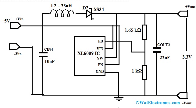
The required components to make this circuit mainly include; XL6009 IC, 33uH Inductor, SS34 Schottky diode, 22uF and 10uF Capacitors, resistors 1.65 kΩ and 1 kΩ. Connect the circuit as per the diagram shown below.

DC Boost Converter Circuit with Xl6009 & SS34 Schottky Diode
Working
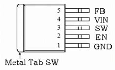
Boost converter circuits are generally designed in different ways so here we are designing with a very popular XL6009 DC to DC Converter IC because these ICs are beginner-friendly and simple to use. The pin configuration of this XL6009 IC is shown below.

XL6009 IC
- Pin1 (GND): It is a ground pin.
- Pin2 (EN): It is an enable pin. When this pin is low the device will be turned OFF and when this pin is high, the device will be turned ON.
- Pin3 (SW): It is a power switch o/p pin.
- Pin4 (VIN): It is a supply voltage pin.
- Pin5 (FB): It is a feedback pin that detects the o/p voltage and changes it using an external resistor divider network.
This XL6009 IC has a metal tab that is connected internally to the Switching pin of this IC.
This IC operating voltage is 5V to 32V. Its switching frequency is 400 kHz and this IC supports a 4A of maximum output current. The DC to DC boost converter circuit using IC XL6009 is shown below. By using this circuit, we can attain a stable 3.3V DC voltage o/p for the 5V input voltage. The SS34 Schottky diode in this circuit is a high-power surface mount Schottky rectifier with a 0.5V low voltage drop & 3A of high forward current. This diode has high efficiency & high surge current capacity. Generally, the Schottky diode as the rectifying element is necessary in boost converter circuits because of the low forward voltage & quick turn-on time of the diode. These characteristics can make the boost converter have better efficiency.
The maximum voltage drop of this diode is around 0.2V across it while 0.1A of current flows throughout it. When the current flowing increases then the Voltage drop across this diode can also increase. So the maximum current flowing through this diode is 3A whenever the voltage drop across this diode is 0.5V only.
To get the necessary output, this IC XL6009 must be configured by modifying the feedback voltage. This voltage can be changed by modifying the resistor’s R5 & R6 values. These two resistor values can be decided by using the formula Vo = 1.25(1+R5/R6).
The reference IC voltage Vref = 1.25. Here, we require Vo = 3.3Vols, then assume either the R5 resistor value or the R6 resistor value, and then get for the other.
For instance; if you select R6=1.kΩ, then substitute this value in the above formula we can obtain R5=1.65kΩ. Thus, the values have a feature of thermal shutdown, preventing the module from overheating in the occurrence of a circuit breakdown. This boost converter normally delivers 94% of output efficiency when it operates at a 400 to 480 KHz frequency range. This dc to dc boost converter is used in High-efficiency-based DC-to-DC voltage conversion and electronic device applications.
Advantages & Disadvantages
The advantages of the SS34 Schottky diode include the following.
- These diodes have majority charge carrier conduction.
- These diodes have a low-forward voltage drop.
- These are very simple to pick & place.
- These diodes have high surge current capacity & high efficiency.
- It has extremely fast switching action.
- These are applicable in high-frequency-based switching circuits.
- These diodes have fewer power losses, high frequency, guarding for over-voltage protection, and low-profile package and these are perfect for automated placement.
The disadvantages of the SS34 Schottky diode include the following.
- This diode has a fairly high reverse current.
- These diodes are susceptible to leaking current whenever voltage is connected in reverse due to its metal-semiconductor junction.
- These diodes have fewer maximum reverse voltages.
- These diodes have high leakage current and reverse leakage current.
Applications
The applications of the SS34 Schottky diode include the following.
- SS34 Schottky diode is used to avoid reverse polarity trouble.
- It is used as a protection device & current flow regulator.
- It is used in high-frequency inverters and current flow regulators.
- These diodes are used in secondary rectification, polarity protection & freewheeling applications.
- This diode is suitable in dc-to-dc converters and low voltage and high frequency based inverters
- It is suitable for use in low-voltage high-frequency inverters, dc-to-dc converters, and applications.
- These Schottky diodes are used frequently in voltage buck/boost circuits.
- These are used in SMPS (Switching mode power supply), adapters, and lighting applications.
- These Schottky diodes can replace typical silicon diodes easily by lower current ability & a higher forward voltage for better efficiency or performance.
Please refer to this link for the SS34 Schottky diode datasheet.
Thus, this is an overview of the SS34 Schottky Diode, pin configuration, specifications, circuit, advantages, disadvantages, and applications. This is a high-power SMD Schottky Diode including 0.5V of low voltage drop, 3A of high forward current, 100A of high surge current & high efficiency. These diodes are used in DC/DC converter, reverse polarity protection & freewheeling applications. Here is a question for you, what is the SS36 Schottky diode?