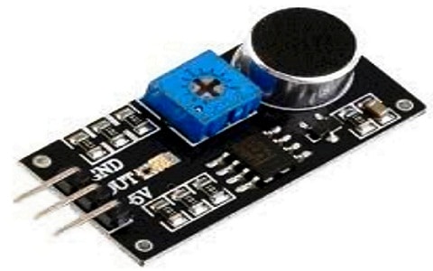
The small board with an electret mic (microphone) and some processing circuit that receives the acoustic signals/sound traveling through the free space/air and converts them into electrical signals is a sound sensor. The output of the sound sensor can be analog or digital output. It is very easy to use, cost-effective, low power, compatible with standard controls and digital/analog ICs. It is easy to integrate logic modules into sensor inputs, and requires a minimum number of external components. This article gives a brief description of the working principle, circuit diagram, and interfacing of the sound sensor with Arduino.
What is a Sound Sensor?/Sound Sensor Definition
The sound sensor is a module that monitors and detects the sound signals like voice, claps, snaps, knocks, etc. It is also known as an acoustic sensor or sound detector. Used in various applications such as security systems, monitoring systems, radios, telephones, mobile phones, computers, home automation systems, consumer electronic appliances, etc.

Sound Sensor IC
It contains a microphone, power amplifier, and output actuator. The microphone that acts as an input sensor receives the sound signal and converts it into an electrical signal. Then this signal is amplified by the power amplifier and its amplitude is detected by the peak detector. The output actuator, like a loudspeaker, converts this amplified electrical signal into a sound signal for listening.
The sound sensors can detect sound signals in the frequency range of 3kHz to 6kHz and it operates at a DC voltage of 3.3V to 6V. It is a small and cost-effective sensor.
Sound Sensor Working Principle
The sound sensor working principle is simple and very easy. It works like a human ear. The sound sensor module consists of a small circuit board that is a microphone of 50 Hz-10 kHz and operates with the sensor detector module for detection. Other external processing circuitry components convert sound waves into electrical signals.
Another important hardware component is the high precision comparator LM393N. This device is mandatory to digitize the electrical signal to the digital output D0. To adjust the sensitivity of the digital output D0, the sound sensor module contains the built-in potentiometer. The basic working principle of a sound sensor is explained in the figure shown below.
The sound sensor contains a microphone called a condenser microphone with 2 charged plates- one is a diaphragm and the other is a backplate. These plates seem like a capacitor. If the sound signals (claps, snaps, knocking, alarms) or audio signals travel through the air and strike the microphone’s diaphragm, then the distance between the 2 charged plates changes due to the vibration of the diaphragm.
Therefore this change in the capacitance between the plates generates the output electrical signal. This output signal is proportional to the input sound signal received by the microphone. Finally, the output signal is amplified by the amplifier and digitized to determine the intensity of the incoming sound signal.
Sound Sensor Circuit Diagram
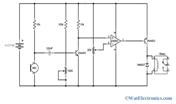
The sound sensor circuit can be implemented by using operational amplifiers and comparator chips. The sound sensor circuit diagram using the LM393N comparator chip is shown in the figure below. This simple switch circuit is used in electrical appliances like fans, tube lights, radios, etc, and in any other applications to turn ON/OFF LEDs and sound.
The above sound sensor circuit is built with a dual voltage LM393N comparator, 2N4401 transistor, 2N4403 transistor, resistors of 10K, 100K, 10K, 20K, and 100K (variable), 120nF, IN4001 diode, relay, an electret mic, and DC supply 9V-12V.
A dual voltage comparator LM393N IC contains 2 comparators integrated into an 8-pin DIP chip. In the sound sensor switch circuit, only one of the two LM393Ns is used, which acts as the heart of the circuit.

Sound Sensor Switch Circuit Diagram
When the audio input comes from an electret microphone, the 120nF capacitor blocks the DC component of the received sound and allows only the AC to flow through the 2N4401N transistor. This AC signal now serves as a control signal for the base terminal of the 2N4401 transistor. The voltage level of the signal can be controlled by a voltage divider network. The audio signal is amplified by the 2N4401 received from the electret mic.
After that, this amplified signal is fed to the LM393N dual voltage comparator IC, and the output is obtained from the ICs output pin-8. To drive the SPDT (single pole dual throw) relay switch, a 2N4403 PNP transistor is utilized at the output of the IC. To adjust or vary the sensitivity of the sound sensor switch circuit, variable resistors of 100K and 20K are used. Generally, the circuit’s operating voltage ranges from 9V to 12V DC and also at a low operating voltage of 3V to 6V. So, the type of relay used in the circuit depends on the operating voltage.
Sound Sensor Types
There are 5 sound sensor types, which are dynamic microphone, carbon microphone, ribbon microphone, and piezoelectric microphone. These are explained below.
Dynamic Microphone
This type of sound sensor is most commonly used in musical and stage performances and many other applications. It is a simple and cost-effective standalone microphone. It works on the principle of electromagnetic induction. It is designed with the diaphragm to which a magnet and coil are fixed. When the sound wave hits the membrane, the coil moves back and forth in the magnetic field due to the induced electric current of the incoming sound vibration. This type of microphone is durable and can handle high-frequency sounds without any distortions and an internal amplifier.
Carbon Microphone
This is the earliest and first microphone form of sound sensor. Its working depends on changes in resistance due to carbon granules. When the carbon granules are compressed, the resistance decreases and provides good electrical contact. compression reduces the drag of the carbon particles. It contains carbon particles in a container enclosed in a small tube protected with a small diaphragm. A battery is required to power through the microphone.
When a sound wave hits a microphone membrane or diaphragm, it vibrates and exerts varying pressure on the carbon. These different pressures (changes) are converted into different resistance levels, which in turn change the current flowing via the microphone. The alternating current can be passed through a capacitor or transformer for use in an amplifier or telephone. This type of sound transducer has a limited frequency response over a narrow range and produces electrical and crackling noises, which can be eliminated by shaking or enabling the carbon granules to produce a steady current.
Ribbon Microphone
It consists of a strip of aluminum ribbon along the edge between the magnet poles. The small gap between the ribbon edges on the sides of the magnet, allows it to move at the speed of air rather than the negative pressure acting on the magnet. So, this microphone is also called a speed/velocity microphone. This has a simple electrical design without any active components. Historically, it has been very popular for high-quality audio applications.
Condenser Microphone
It has a wide frequency response and is capable of producing high-quality sound. It consists of a thin membrane near a rigid metal plate that acts like a metal diaphragm and is electrically conductive. Older microphone types used thin metal foil, while newer microphone types used plastic, gold, or aluminum-coated microphones. For example, sputtered mylar with gold. The configuration produces capacitors ranging from 10-50 pF. This sensor requires a constant power supply (DC), which can be supplied by a battery or coaxial line.
If the power is supplied over a coaxial line, then it is phantom power. The applied voltage pulls the membrane tightly. When a sound wave hits the microphone, the membrane moves back and forth. This results in a change in capacitance. This change in capacitance, in turn, causes a change in voltage.
These microphones require a buffer amplifier due to the high impedance. It is not as powerful as a dynamic microphone as its internal construction is very smooth. It doesn’t work perfectly in humid environments because high humidity conditions can cause internal flames between the microphone element back plate. This microphone is very sensitive and can be overloaded with loud sounds. Therefore, care should be taken when selecting this type of sound transducer for non-overloaded applications.
Sound sensor Module
The module that is used to detect the sound or audio signal intensity in several sound detecting applications such as switches, security systems, home automation systems, monitoring systems, etc, is called the sound sensor module.
It contains a microphone to detect the presence of sound signals. It is also used to detect the frequency of the noise signals ranging from 3kHz to 6kHz. It contains various components such as a microphone with the diaphragm to convert the sound signal into analog/digital output signals, an LM393 comparator, and an in-built potentiometer for sensitivity adjustment.

Sound Sensor Module
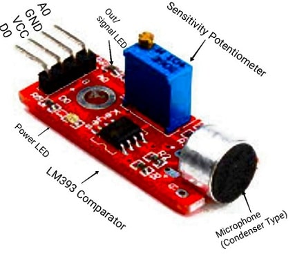
The sound sensor module is available as KY-038 with 4-pins, which are explained below. The pin diagram of the sound sensor module is shown below.
The sound sensor module contains 2 onboard LEDs (signal/output and power LEDs), a potentiometer, an LM393N voltage comparator, and a microphone. This module is used to design sound reactive switches and LED visualizers.
Power LED: This LED starts blinking when the positive voltage supply is given to the module.
Out/Signal LED: This LED starts blinking when the input sound/audio signal exceeds the threshold value of the module set by the onboard potentiometer.
In-built Potentiometer: This is used to change Or adjust the sensitivity of the module regarding the sound signal hit by the microphone.
Microphone: When the sound signal strikes the diaphragm of the microphone, the output audio signal is generated.
LM393N Comparator: The audio signal generated by the microphone is amplified and converted into a digital signal for determining the intensity of the input signal.
- Pin 1 (VCC): This pin is used to give a positive power supply of 3.3V to 6V.
- Pin2 (GND): This pin is used for common ground connection.
- Pin3 (Analogue output A0): This pin is used to obtain the analog output signal from the module. It is connected to the analog pin of the microcontroller or Arduino during interfacing.
- Pin4 (Digital output D0): This pin is used to obtain the digital output signal from the module. The signal is detected by the sensor, then the D0 will be high otherwise it will be low.
Specifications
The sound sensor module specifications are given below.
- Wide operating voltage of 3.3V to 5V DC.
- Operating current of 4mA to 5mA.
- The voltage gain of 26dB.
- The high sensitivity of 1KHz.
- Microphone’s dB level of 52 to 48dB.
- The impedance of the microphone is 2.2-kilo ohms.
- The frequency of the microphone is 16KHz to 20KHz.
- The signal-to-noise ratio is 54dB.
- LM393N comparator with threshold present is used.
- The induction distance is 0.5 meters.
Sound Sensor Interfacing with Arduino
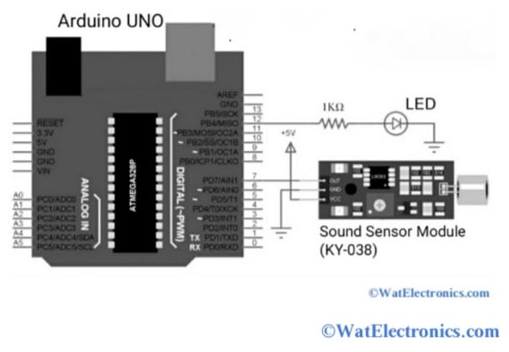
In this section let’s see how to interface the sound sensor module with Arduino UNO. It is very easy and doesn’t require additional soldering, jumper wires, or breadboard. The circuit diagram of the interfacing sound sensor with the Arduino is shown below. The components required are,
- Sound sensor module
- Arduino UNO.
- LED
- Resistor kilo Ohms.
- Mini breadboard
- Connecting wires.

Interfacing Sound Sensor Module with Arduino
Connections are made as per the above circuit diagram. The +5V pin and GND pins of the Arduino are connected to the VCC and GND pins of the sound sensor module. The digital input pin 7 of the Arduino is connected to the output pin D0 of the sensor module. The 1-kilo ohms resistor with the LED is connected to pin 12 of the Arduino. And the other terminal of the LED is grounded.
Sensor Module Arduino Code:
Upload the below Arduino code to obtain the output.
const int ledPin = 12;
const int soundPin = 7;
int soundVal = 0;
void setup ()
{
pinMode (ledPin, OUTPUT);
pinMode (soundPin, INPUT);
}
void loop ()
{
soundVal = digitalRead(soundPin);
if (soundVal == LOW)
{
digitalWrite(ledPin, HIGH);
}
else
{
digitalWrite(ledPin, LOW);
}
}
The LM393N comparator in the sound sensor module extracts the audio signal or any sound from the microphone and produces the digital output at the output pin D0 of the module. After uploading the Arduino code, clap or snap sounds are made in front of the microphone of the sensor. Then observe the status of the LED, which is connected to the digital output pin 12 of the Arduino and also at the digital pin 7 of the Arduino connected to the D0 of the sensor module.
The LED blinks when the sound or audio signal is detected by the sensor. To calibrate the sensor (its output) and set its threshold value, the built-in potentiometer is adjusted by turning the knob. The potentiometer can be adjusted until the LED starts blinking. When the sounds made near the microphone exceed the particular limit of the sound sensor, then the output D0 will be low.
The sound signal intensity (High/Low) is detected by observing the sensor’s output (High/Low).
Note: To interface the sound sensor module with any microcontroller, the ADC pins of the Arduino UNO are utilized for processing if the sound sensor module gives the analog signal at the A0 pin.
Advantages and Disadvantages
A few advantages of sound sensor are given below
- These are suitable for security systems.
- These are used in speech recognition software to convert speech or sound into text format. This approach is faster than manual typing. So, these are used by disabled persons.
- Very easy in sound manipulation in real-time applications without any requirement of earlier recordings.
- Used by switching ON the radio while driving to improve safety. Here, the sound sensor works based on the voice activation system.
- Available at affordable rates.
- Wireless sound sensors are easy to handle and don’t require any cabling when compared to a mic (wired).
The disadvantages of the sound sensor are given below:
- More memory size is required to store sound files.
- Sound sensors based on voice recognition software are inaccurate.
- The cost of the microphone is increased to suppress the interference of the nearby radio signals.
- Wireless microphones are used for only a limited range.
- The wireless microphones’ operating time is limited due to battery life and other issues.
Applications
The following are the sound sensor applications,
- Home automation systems like controlling the lighting of the bulbs by detecting the claps/whistles sounds.
- Recording studios to record the audio.
- Communication devices like mobile phones, laptops, robotics, music players, etc.
- Spy systems, security systems, and monitoring systems such as door alarms, burglar alarms, etc.
- Audio amplifiers, sound level, and ambient sound recognition systems.
- Used in sound pressure level devices.
Know more about Interfacing Knock Sensor.
Thus, this is all about the working of the sound sensor and interfacing the sound sensor with Arduino. The different types of sound sensor modules are designed with different comparator ICs like LM393, LM324, LM344, and LM386. Check the design specifications and select the sound sensor module that suits the application or project.