Capacitors’ invention was initiated in the beginning days of electricity. In the initial days of development, capacitors were called condensers. This term was primarily utilized for the objective of high-power applications by Alessandro Volta in the year 1782. Thereafter, the term condenser was not in usage because of the complicated meaning of steam condenser and replaced by the name ‘capacitor’ in the year 1926. Now, this article provides a clear analysis of one foremost type of capacitor which is ‘shunt capacitor’, what is its working, advantages, and uses.
What is Shunt Capacitor?
In the scenario of electrical systems, the widely used component is capacitor bank. The power necessary to operate the entire electrical device is the load which is active power which is measured either in kilowatts or megawatts. The maximum amount of load that can be connected to the power system has inductive nature like electric furnaces, induction motors, and synchronous type of motors.
Due to these inductances, the system voltage stands ahead of the system current. When the lagging angle in between current and the voltage gets increased, there will be a reduction in the system’s power factor. When there is a decrement in the power factor for the same amount of active power, then the system receives more amount of current from the source which leads to losses. Whereas less amount of power factor leads to weak voltage regulation.
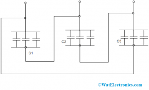
In order to get rid of all these complexities, the power factor has to be increased. As the functionality of the capacitor allows current to take the lead of voltage levels, capacitor reactance might be utilized to revoke the system’s inductive reactance. This capacitor reactance is usually used for the system through static capacitors either in series or shunt connection with the system. For this, a capacitor bank is used. And the capacitor banks are mainly of two types which are shunt and series type. The shunt capacitor diagram is shown below:

Wiring
Rating of Capacitor Bank
The capacitor bank’s rating can be known by implementing the below-stated formula which is
Q = P(tanϴ – tanϴ’)
Here, ‘Q’ corresponds to the amount of necessary KVAR
‘P’ corresponds to active power measured in kilowatts
‘cosϴ’ corresponds power factor before the compensation
cosϴ’ corresponds power factor after the compensation
With the above formula, one can know how to determine the rating of the required capacitor bank.
How to Connect Shunt Capacitor Bank?
The connection of the shunt capacitor bank can be arranged either in star or delta format. In the star type of arrangement, the neutral point is connected to the ground or else based on the protection arrangement for the bank. In few scenarios, the arrangement of capacitor bank can also be in double star format.
Mostly, huge capacitor banks that are used in electrical substations are in the form of star arrangement. This type of connection shows some particular benefits like
- Installation cost is not more
- Enhanced surge protection
- Minimal recovery voltage in the case of circuit breakers for general recurring capacitor switching interruptions
- In the case of rigid grounded systems, the voltage level for the entire three phases in the capacitor bank is constant and continues to be the same even for a 2-phase functioning period
Location of Shunt Capacitor
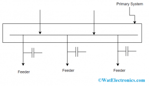
Hypothetically, it was clear that the capacitor bank is always authorized to be close to the reactive load. This allows the communication of reactive type of KVARS is eliminated from the network. Additionally, when the load and the capacitor are concurrently connected, then at the time of disconnection, the capacitor is also removed from the circuit. So, there will be no compensation issues. Whereas when the connection is in the form where the capacitor connects with every separate load is not possible practically.
Because every load size has its own size and also varies based on consumers. Thus, because the size of the capacitor is not immediately available. So, accurate compensation is not feasible at every loading terminal. Also, there will be no continuous connection between the system and load. So, the connection that is between load and capacitor is not always completely used.

Shunt Capacitor Location
Therefore, only for medium and large loads the only capacitor is installed but not for minimal loads, capacitor bank can be used at the customer’s own locations. Even though inductive loads which are of medium and huge bulk customers are compensated, still there exists some VAR that is developed from various uncompensated minimal loads that have a connection with the system.
Furthermore, the transformer’s and line inductance values also drive VAR for the system. With all these complications, other than establishing a connection between load and capacitor, a huge capacitor bank is used at the location of the main distribution sub-station or else at the secondary grid located sub-station.
Advantages
The advantages of shunt capacitor include the following.
- For a specific range of active power, the delivered demand of kVA is lessened. Thus, because more machines can be installed for a provided range of kVA load
- As there is a reduction of voltage drop, there will be an increment in the motor torque ability. With this, the take-off time and heating of the motor will be minimized. The necessity of the motor current for a similar range of output is less.
- As there is less heat released by the motor, the aging period is less and so the machine’s life and the cables will be augmented
- The switchgear tear and wear is reduced due to the reason of minimal arching energy dissipation at an increased power factor
- As the losses in the feeders are reduced, there will be minimal voltage drop so this enhances voltage regulation.
Know more about Power Capacitor.
Please refer to this link to know more about Capacitors MCQs
This is the detailed concept of a shunt capacitor. This article has explained clearly shunt capacitor rating, location, connection, and advantages. Also, know about the shunt capacitor applications and how they are used for various purposes?