As already known the purpose of the rectifier is to convert alternating current (AC) into direct current (DC). It is the basic unit of any DC supply. The designing of the rectifier and its suitability for practical applications is dependent on the characteristics of that particular rectifier. Its characteristics include RMS value, average output value, ripple factor, peak inverse value and so on. After the completion of the process of rectification, the output DC generated consists of some AC components in it. This indicates that output is not in the pure form. This is measured in terms of ripple factor. So here the important topic of concern is the ripple factor of the rectifiers.
What is Ripple Factor?
After the process of rectification if the output generated consists of some AC components in it are referred to as ripples. These ripples are measured in terms of Ripple Factor. The ratio in between the RMS value of the particular AC components present in the output to the presence of DC in that particular output generated is referred to as ripple factor denoted by ‘r’.
r=Irms/IDC
For any rectifier to measure its effectiveness ripple factor is utilized. Let us discuss the information regarding the ripple factor with the two basic rectifier’s half-wave and full-wave.
Introduction to the Basic Model of Half Wave Rectifier
It is a basic model of the rectifier. In this, only a single diode is used for the purpose of rectification. Here only a single cycle of the input is utilized during rectification other cycle gets blocked. Hence there is a loss of power in the circuitry. The basic model consists of a semiconductor diode connected in series with the supply and the load resistor. The functionality and the output obtained depend on the type of cycle chosen either positive or negative.
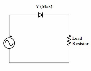
half wave rectifier
If the cycle considered is positive then in that case as per the basic functionality of the diode it will be in forward bias and it allows the path for the flow of current in the circuit. It blocks the negative cycle. This is referred to as a positive half-wave rectifier. The only change made if the negative cycle is to be considered is that change in the direction of the diode-connected. Then the remaining process remains the same. Now it is referred to as negative half-wave rectifier.
However, the output generated consists of ripples. This can be eliminated by connecting a capacitor across the load. This capacitor functions as the filter and smoothens the output obtained from the rectifier.
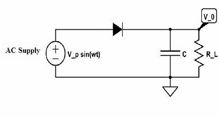
half wave rectifier with capacitor filter
Once the circuit is connected to the supply if the positive cycle is supplied then capacitor gets enough charged and it holds the voltage of the diode at its peak value and after that capacitor tends to degrade at the load slowly because of reverse bias condition in the diode.
Ripple Factor for the Basic Model of Half Wave Rectifier
Generally, the ripple factor for the basic half-wave rectifier is
r=Irms/IDC
The RMS value of the AC component in the output is defined as
Irms=Im/2
The DC value of the output wave is
IDC= Im/π
The I_rrms value can be obtained by
Irrms=√(Irms)2-IDC)2
After substituting the values and the further simplification results in obtaining the final value of the ripple factor as r=1.21
Ripple Factor of Half Wave Rectifier with Capacitor Filter
After the rectification, the capacitor is connected across the load for further smoothening. This capacitor has the phenomenon of charging and discharging. This results in the induction of ripple voltage. As the capacitor filter is connected the ripple factor gets reduced.
Hence the ripple factor for the half-wave rectifier with capacitor filter is given by
r=1/(2√3 f RLC)
Here the ‘f’ stands for the frequency of the DC wave that obtained after rectification in the form of pulses. It is the same as that of the applied AC frequency. Based on the output voltage the value of the ripple factor can be estimated as
r=(Vrpp/2√3)/(Vp – 0.5Vrpp )
The peak value for the output voltage is denoted as Vp and peak to peak ripple voltage value can be referred to as Vrpp.
Introduction to the Full Wave Rectifier Circuit
The main drawback of a half-wave rectifier is that it utilizes only one cycle during rectification resulting in the loss of power. This can be overcome by the full-wave rectifier. In the full-wave, both the cycles are utilized for rectification. Hence the circuit minimizes the loss in power. Full-wave is classified into two types.
(1) Center-Tapped Transformer
In this, the basic transformer with a wire at the center of the secondary winding is tapped. Hence it is known as a center-Tapped transformer. The two diodes are connected in parallel to the resistive load. If the positive half of the cycle is applied as the input in that case diode D1 will be in forward bias whereas D2 remains in reverse bias.
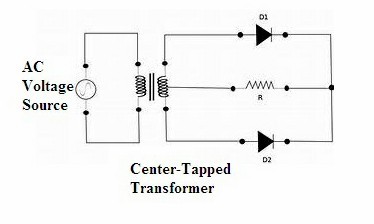
Full Wave Rectifier (Center-Tapped)
If the negative cycle is considered in that case one diode acts in forward and the other in reverse. But the transformer utilized here is costly. Hence the other model of full-wave rectifier has been designed.
(2) Full Wave Rectifier (Bridge)
The positive and the negative halves of the input are utilized here for rectification. In this type rather than considering a transformer that is center-tapped a rectifier is designed by connecting four diodes in a bridge topology. The diodes that are connected in a diagonally opposite facing follows the same bias and the rest of the two will remain oppositely biased. Hence this is referred to as Bridge rectifier.
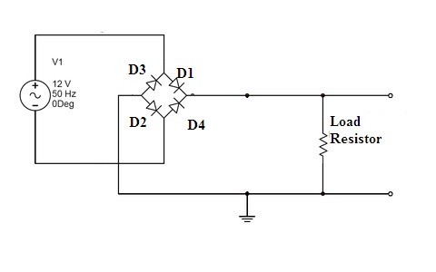
full wave rectifier (bridge)
However, the output generated will consist of some ripples in the output. This can be made more effective by connecting a capacitor across the load for the filtering of the rectified output.
Ripple Factor of Full Wave Rectifier (Similar for Both Centres- Tapped as Well As Bridge)
Here the ripple factor is given by
r=Vrrms/VDC
The Vrrms is the ripple factor of the peak to peak is
Vrrms=√Vrms2– VDC2
Vrms is the RMS value of the voltage it is given by
Vrms=Vm/√2
The output DC value can be given as
VDC= (2Vm)/π
On substituting and solving results in the value of the ripple factor of the full-wave rectifier as r= 0.483
Ripple Factor of Full Wave Rectifier with Capacitor Filter Derivation
Here the output waveform generated as per the characteristics of capacitor involved with the rectifier circuit is considered in order to analyze the ripple factor of the full-wave rectifier.
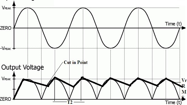
output waveforms of full-wave rectifier with capacitor filter
The charge of the capacitor acquired is referred to as
Vrrms*C
Charge lost on it is given as
Idc*T2
However, both the equations of acquired and lost are equated
Vrrms*C = Idc*T2
If the considered capacitor or the resistor of the filter is large enough then
T2 = T/2 = 1/2f
Then,
Vrrms = Idc/2fC
As per the assumptions based consider that ripple factor waveform in the shape of a triangle
Vr rms=Vrrms/(2√3)
On substituting the known value of Vrrms the above equation can be rewritten as
Vrrms=Idc/(4√3 fC)
Therefore by the concept of ohms law;
Idc=Vdc/RL
Then,
Vrrms=Vdc/(4√3 fCRL )
(Vrrms)/Vdc =1/(4√3 fCRL )
Know more about Rectifiers MCQs.
From the above equation, it is clearly evident that the value of the ripple factor in the output signal is inversely related to the value of the capacitor and the resistor. Hence from the above analysis, the necessity of the filtering circuit after the rectification of the output is clearly evident. The importance of the capacitor filter is analyzed here. Similarly, can you compare the capacitor filter with the inductor filter and decide which one is well suited?