RF Transceiver
Generally, an RF module is a small size electronic device, that is used to transmit or receive radio signals between two devices. The main application of the RF module is an embedded system to communicate with another device wirelessly. This communication may be accomplished through radio frequency communication. For various applications, the medium of choice is radiofrequency since it does not need a line of sight. The applications of RF modules mainly involve low volume and medium volume products for consumer applications like wireless alarm systems, garage door openers, smart sensor applications, wireless home automation systems, and industrial remote controls. This article discusses the block diagram of the RF transceiver module and its applications.
What is an RF Transceiver?
A transceiver is a blend of a transmitter and a receiver in a single package. The name applies to wireless communication devices like cellular telephones, handheld two-way radios, cordless telephone sets, and mobile two-way radios. Sometimes the term is used in reference to the transmitter or receiver devices in optical fiber systems or cables.
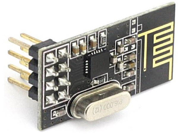
RF Transceiver Module
In a radio transceiver, the receiver is silenced while transmitting. An electronic switch permits the transmitter and receiver to be allied to the same antenna and stops the o/p of the transmitter from injuring the receiver. With this kind of transceiver, it is difficult to get signals while transmitting and this mode is named half-duplex.
Some kind of transceiver is designed to let reception of signals through transmission periods. This mode is called full-duplex and needs that the transmitter (TX) and receiver (RX) work on considerably different frequencies so the signal which is transmitted doesn’t interfere with reception. Communication device sets use this mode. Satellite communication networks frequently employ full-duplex transceivers at the surface-based subscriber points. The transceiver-to-satellite (transmitted) signal is called the uplink, and the satellite-to-transceiver (received) signal is called the downlink.
Block Diagram of RF Transceivers
In general, the designer of wireless systems has two overriding limitations: it must work over a convinced distance and transfer a convinced amount of information within a data rate. The size of the RF modules is very small and has an extensive range of operating voltage that is 3V to 12V.
Basically, these modules are 433 MHz RF TX and RX modules. The transmitter (TX) draws no power when transferring logic zero while fully destroying the carrier frequency, thus consume considerable low power in battery operation. When logic1 is sent carrier is fully on to about 4.5mA with a 3V power supply. The information is sent serially from the transmitter (TX) which is received by the receiver. The transmitter (TX) and the receiver (RX) are duly interfaced to two Microcontrollers for transferring the data.

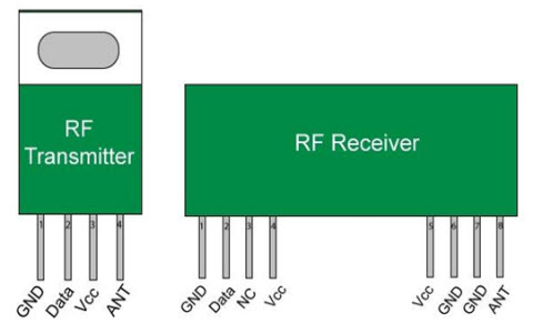
RF Transceiver Block Diagram
RF modules can be applied for various types, sizes, and shapes of electronic circuit boards. It can also be useful for modules across a vast variety of capacities and functionality. These modules typically include a PCB, TX circuit or RX circuit, antenna, and a serial interface for communication to the main processor. The types of RF modules mainly include RF transmitter module, RF receiver module RF transceiver module, and SOC module. There are 3-types of signal modulation techniques commonly used in RF transmitter and RF receiver modules such as ASK-amplitude shift keying, OOK-On-Off Keying, and FSK-frequency shift keying
An RF transceiver module includes both a transmitter and receiver. The circuit of the RF transceiver module is typically designed for half-duplex operation and although full-duplex modules are available, they typically at a higher cost due to the added complexity.
RF Transmitter
An RF transmitter module is a small size PCB capable of transferring a radio wave and modulating a radio wave to carry data. RF transmitter modules are usually applied along with a microcontroller, which will offer data to the module which can be transmitted. These transmitters are usually subject to controlling requirements that command the maximum acceptable transmitter power o/p, band edge, and harmonics requirements.
RF Receiver
An RF receiver module takes the modulated RF signal to demodulate it. There are two kinds of RF receiver modules, namely the super-regenerative receivers and super-heterodyne receivers. Usually, super-regenerative modules are low power designs and low cost using a series of amplifiers to remove modulated data from a carrier wave.
These modules vary, generally inaccurate as their operation of a frequency significantly with power supply voltage and temperature. The main advantage of Superheterodyne receiver modules is a high performance over super-regenerative. They offer increased stability and accuracy over a large temperature and voltage range. This stability comes from a stable crystal design which in turn leads to a relatively more expensive product.
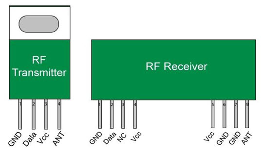
RF Transmitter and Receiver
RF transceiver module is used in a particular device where both the transmitter and receiver housed in a single module. Such devices transmit and receive RF signal, so that is named as RF Transceiver. Mostly the position of the RF Transceiver module is in between Power amplifier/Low Noise Amplifier and Baseband MODEM in any wireless communication system. Baseband Modem houses, chipsets of several analogs or digital modulation techniques and analog to digital conversion or digital to analog conversion chips.
RF Transceiver module design is made up of amplifiers, RF Mixers, pads & other RF components using microstrip technology. The transmitter and Receiver parts in the RF transceivers called RF Upconverter and RF Downconverter.
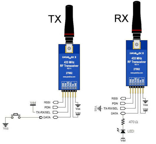
Technical Specifications of RF Transceiver
There are so many parameters related to RF Transceiver
- The parameters in the RF transmitter part include gain flatness, i/p, and o/p frequency range, gain adjustment, conversion gain, compression point, 1dBm frequency stability, spurious & harmonic o/p.
- The parameters on the receiver part include input & an output frequency range, gain flatness, gain adjustment, spurious output, noise figure, Image rejection, adjacent channel, nonadjacent channel, and rejection frequency stability.
Technical Specifications of RF Transceiver
Applications of RF Transceiver
- RF transceiver module is used in wireless communication. The main application of this transceiver is to make information in the form of data/voice/video apt to be transmitted over the wireless medium.
- The main intention of this device is to alter IF frequency to RF frequency and vice versa.
- RF transceiver module is used for radio transmission, satellite communication, television signal transmission, reception, and in Wimax or WLAN, Zigbee, or ITE networks.
For a better understanding of this concept, here we are explaining some projects as an application purpose
RF-based Home Automation System
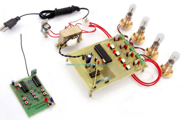
RF-based Home Automation System Project kit
The main goal of this project is to design a home automation system controlled by an RF remote. Nowadays, technology is improving day by day. By using wireless technology, we can avoid difficulty for the user. If the user is physically handicapped, or even more elder, then they will face a lot of difficulties. Because they need to go near to conventional wall switches to operate and these switches are located in different parts of the house. With the use of RF-controlled switches, modern houses are shifting from conventional switches to centralized control systems. By using wireless technology, the loads can be turned ON/OFF remotely with the specified remote operation. In order to achieve this, an RF remote is interfaced to the microcontroller at the end of the transmitter section which sends ON/OFF commands to the receiver end, where loads are connected.
Some More Project Ideas based on RF
The list of some more RF-based project ideas is listed below.
- Patient health monitoring system with location details by GPS over GSM
- Voice Controlled Home Appliances
- Voice Controlled Robot by Cell Phone with Android App
- Wireless Home Appliance like Fan Speed Control using RF Communication
- Wireless DC Motor Speed and Direction Control for Robotic Applications
- Urban Traffic Signal Based on Density and also with the Remote Override
- Wireless Rash Driving Detection
- Voice Controlled Robotic Vehicle with Long Distance Speech Recognition
- Density Based Traffic Signal with Remote Override in Emergency
- Speed Synchronization of Multiple Motors In Industries using PIC Microcontroller
- War Field Spying Robot with Night Vision Wireless Camera
- Fire Fighting Robotic Vehicle
- Pick N Place with Soft Catching Gripper
- Metal Detector Robotic Vehicle
- RF-based Home Automation System
- RF Controlled Robotic Vehicle with Laser Beam Arrangement
- Touch Screen based Home Automation System
- Secret Code Enabled Secure Communication using RF Technology
- Unique Office Communication System Using RF
- Speed Synchronization of Multiple Motors in Industries
- Automatic Wireless Health Monitoring System in Hospitals for Patients
Thus, this is all about block diagram and explanation of RF transceiver includes what is RF module, RF transmitter, RF receiver, a block diagram of RF transceiver module and applications of RF transceiver. We hope that you have got a better understanding of this concept. Furthermore, for any queries regarding this concept or electrical and electronics projects, please give your valuable suggestions by commenting in the comment section below.
Please refer to this link to know more about Yagi Uda Antenna MCQ’s, SCADA MCQ’s & GSM MCQs.
Photo Credits:
- Technical Specifications of RF Transceiver parallax