Resistors are essential components in electrical and electronic circuits which are used in different electronic devices. There are different types of resistors available but based on the type, their properties may vary. These properties will assist you while selecting the right type of resistor for designing any circuit. Different types of resistors are used in different applications based on the requirement. So it is compulsory to identify the type of resistor as well, in which the type of resistor is used. Most of the circuits can be designed with these components, so it is impossible to design the circuit without using these components. This article discusses an overview of a resistor.
What is a Resistor?
Resistor definition is a two-terminal electrical and electronic component that is used to restrict the flow of current within the circuit is known as a resistor. And also the main use of resistor is to create fixed current and voltage values within a circuit. In the flow of the current of the circuit, the resistor will create resistance and it is measured in Ohms (Ω).
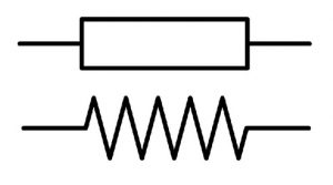
The resistance mainly occurs once a 1-ampere current flows throughout a resistor by a 1-volt drop across its two terminals. The resistor symbol is shown below. So, the flow of current is proportional toward the voltage across the two terminals of the resistor and the ratio can be signified through Ohm’s law:

Symbols
The formula of ohm’s law is V = IR => R = V/I
Resistors are mainly used for several purposes which include restricting the electric current, generation of heat, voltage division, circuits for loading & matching, gain control, and fix time constants. Resistors are available commercially including resistance values with above nine orders of magnitude. The resistor diagram is shown below.

Resistor
The resistors which have high resistance values can be represented through kilo-ohms (K) & Meg ohms (M). For instance, if the resistor value is 120 000 ohms then it can be represented like 120k ohms, whereas the resistor with 1200 000 ohms and can be represented as 1Mega ohms.
In some electrical or electronic circuits, the resistor can be denoted with the ‘E’ letter for resistance within ohms instead of the letter ‘R’ but both are the same. For instance, 47E (47R) stands for 47 ohms 1E2 denotes 1R2, etc.
There are different types of resistors like thermistors, carbon composition, metal film, wire wound, variable, carbon film, LDR, varistors, magneto, fixed, etc.
Construction
The construction of the resistor will change based on the type because there are different types of resistors. Let us discuss some of them.
In a carbon type, the construction can be done by arranging a carbon tubular rod within an insulating ceramic tube. The resistance & tolerance values are normally marked on the component with color bands that ranges from 10 ohms to 1 Mega ohm.
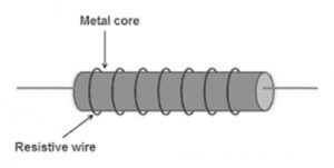
In a wire wound type, a resistance wire is wounded spirally on a tubular ceramic rod and also coated through a heatproof vitreous enamel coating or ceramic. The power rating & the resistance value are generally marked on the component that ranges typically from 0.1 ohms – 10k ohms.

Construction of Wire Wound Resistor
The variable type construction can be done by arranging a carbon track that is circular-shaped through a sliding metal contact that can be driven by using a rotating control shaft. This is also known as a potentiometer and it includes three terminals. The typical resistance values range from 1k ohm to 1 Mega ohm.
Please refer to this link for Resistor MCQs
Resistor Working
The resistor working in the circuit can be compared to the flow of water within the pump because both the working concept is similar. In a pipe, if the diameter is decreased then water flow within the pipe will be decreased.
If the water pressure is increased through increasing the force, then the energy can be dissipated like heat. So, there is a huge difference within force applied at both the pipe ends. The force or pressure which is applied to the water in the pipe is related to the flow of current throughout the resistance. The force applied is similar to the voltage.
Resistor Circuit/Application of Resistor
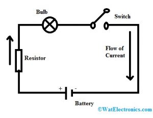
The basic circuit diagram of a resistor is shown below. This circuit can be built with a wire, battery, resistor, switch, and load. A circuit begins at one point and ends at a similar point. Generally in this circuit, as a conductor, a copper wire is used without insulation.

Resistor Circuit Diagram
A switch is mainly used to connect or disconnect a circuit. Resistor restricts the flow of current within a circuit which simply uses power however not produce powers because it is a passive component. Finally, a load uses electrical energy to change it into other energy forms such as heat, light, etc. In this circuit, a light bulb is used as a load.
Resistors in Series Connection
When resistors are connected in series in a circuit then the flow of current in the resistors will be the same and the voltage across every resistor is not the same. In this connection, if any resistor damages then the whole circuit will be switched off. As compared to a parallel circuit, a connection of the series circuit is very simple. The series circuit is shown below. The resistors in the series formula and the whole resistance can be given as
Rtotal = R1 + R2 + R3+….. + Rn
The total resistance of the system is just the total of individual resistances.
Example:
A resistor with 80 ohms electrical resistance is connected to another 100 ohms resistor in series then what will be the total resistance.
We know that two resistance values like R1 = 80 Ω & R2= 100 Ω
Formula for resistors in series can be defined as
Rtotal = R1 + R2 + …+Rn
= 100 + 200 = 300 Ω
Resistors in Parallel Connection
When resistors are connected parallel in a circuit then the voltage across the resistors will be the same.
In this connection, the resistor or any other component can be easily detached without affecting other components. Once branches in the circuit meet at a point commonly, then the flow of current will recombines & branched outs. In the following circuit, the number of resistors is connected in parallel and the resistors in the parallel formula can be given as
1/Rtotal = 1/R1 + 1/R2 + 1/R3 …. + 1/Rn
Example:
Similarly, the same resistance values can be used for parallel connections. What will e the total resistance when connected in parallel in the circuit?
We know that two resistance values like R1 = 80 Ω & R2= 100 Ω
Formula for resistors in parallel can be defined as
Rtotal = 1/R1 + 1/R2 +1/R3 …+1/Rn
= 1/100 + 1/200 = 2+1/200 = 3/200 = 0.015

Series & Parallel Connections
Resistor Tolerance
The tolerance value of a resistor can be observed in 4 color band resistor. Tolerance is the % of error value within the resistance. Typical tolerance values are 5%, 10% & 20%, but also 0.1%, 0.25%, 0.5%, 1%, 2%, 3% & 4%. Here, the tolerance value of gold is 5% and silver is 10%.
For Example
A 220-ohm resistor includes a silver tolerance band.
Tolerance = Resistor Value x Tolerance Band Value = 220 Ohm x 10% = 22 Ohms
Tolerance value plays a major role while identifying the resistor to know which one will give you a more precise resistance value. When the tolerance percentage is less, then the precision within your dimensions will be higher. The tolerance representation can be observed in the 4 band type resistor color code concept and the tolerance values are given in the following table.
|
Band Colors |
Tolerance |
|
Black |
|
| Brown |
±1% % |
|
Red |
±2% % |
|
Orange |
|
| Yellow |
±0.5% |
|
Blue |
±1% |
| Green |
± 0.1% |
|
Violet |
|
|
Grey |
|
|
White |
|
| Gold |
± 5% |
| Silver |
±10% |
|
None |
20% |
Difference between Resistor and Resistance
The main difference between resistor and resistance includes the following.
- It is an electrical component including a fixed electrical resistance value that ranges from 1 Ω, 10 Ω, 100 Ω & 10000 Ω, etc.
- The property of a conductor is known as resistance, which decides the amount of current that flows throughout it once a potential variation is applied across it.
- The circuit design using resistors can be done based on the sum of current you desire to supply throughout a circuit.
- While designing physical boards or actual circuits, dealing with physical components, the two terms can be interchangeable. For instance, if we say a 22 ohms resistor otherwise we can say it as “a 22 ohms resistance.
- It is one kind of component used to restrict electric current while resistance is the intrinsic material property to resist the current flow.
Properties of Resistor
The resistor properties are mentioned below.
- Low TCR (Temperature Coefficient of Resistance)
- Maximum Voltage
- Power Rating
- Thermo-electric Effect
- Noise
- Mechanical Strength
- Dependent on Frequency
- Resistance Value Tolerance
- Insulation of the Wires
- Pulse Stability
- Protection from the Environment
- Durable Stability
- Material’s Electrical Resistivity
Resistor Characteristics
The resistor working can be easily understood through the VI characteristics (Voltage current). Generally, these characteristics illustrate the main relationship between voltage (V) and current (I) for a specific component. For a resistor, these characteristics are pretty linear that as shown in the following graph.
So we can observe that when the current supplies through a resistor then the voltage will be increased across it. Even though, various resistors with dissimilar resistance will provide diverse voltages once the same ampere of current supplies throughout it.
So, the voltage across a resistor is comparative to the flow of current through it. A resistor follows Ohm’s law because the relationship between voltage & current is linear within nature. This law states that the flow of current throughout a conductor can be proportional toward the voltage which is developed across it (V = IR).
Applications
The applications of resistors include the following.
- Wire wound type is used where high sensitivity, precise measurement & balanced control of current are necessary like ampere meters.
- Photoresistors are used in photographic devices, burglar alarms, flame detectors, etc.
- These components are used for temperature control as well as a voltmeter.
- Used in amplifiers, digital multi-meter, oscillators & telecommunication.
- Applicable in transmitters, modulators & demodulators.
- These are used in electronic circuits & electrical networks
- Generally in an electric circuit, a resistor creates an identified voltage to current ratio. If the current is known within the circuit, then it will make an identified potential disparity that is proportional to the current. On the other hand, if the potential disparity among two points within a circuit is identified, a resistor can create an identified current that is proportional to that disparity.
- Two or above resistors are used in an attenuator for reducing the signal voltage
- A line terminator is used at the transmission line end to match impedance & also reduce signal reflections.
- A resistor is connected in series with the LED, and then the flow of current through the component can be reduced to a recognized secure value.
- In electric heaters, resistors will dissolve heat.
Please refer to this link to know more about Wire Wound Resistor.
Thus, this is all about an overview of a resistor, construction, circuit, working & its applications. It is an electrical component that is used to control the current flow within a circuit. When the available current is low for a specified voltage then it is called high resistance. In this component, the collide of electrons can be done with ions, decreasing the current flow while generating heat. Here is a question for you, what are the different types of resistors available in the market today?