The basic p-n junction diode that is used for the conversion of AC to DC can be referred to as a rectifier. This process is known as rectification. Based on its efficiency of converting AC to DC these rectifiers are chosen so that it can satisfy the essential requirements of the power supply unit in the electronic systems. Various basic electrical or electronic components are preferred in order to design rectifiers it can be diodes, MOSFET’S, etc. Considering the suitable application essential components are used and rectifiers are designed. A rectifier consists of single or multiple diodes as the basic necessity of the electronic components.
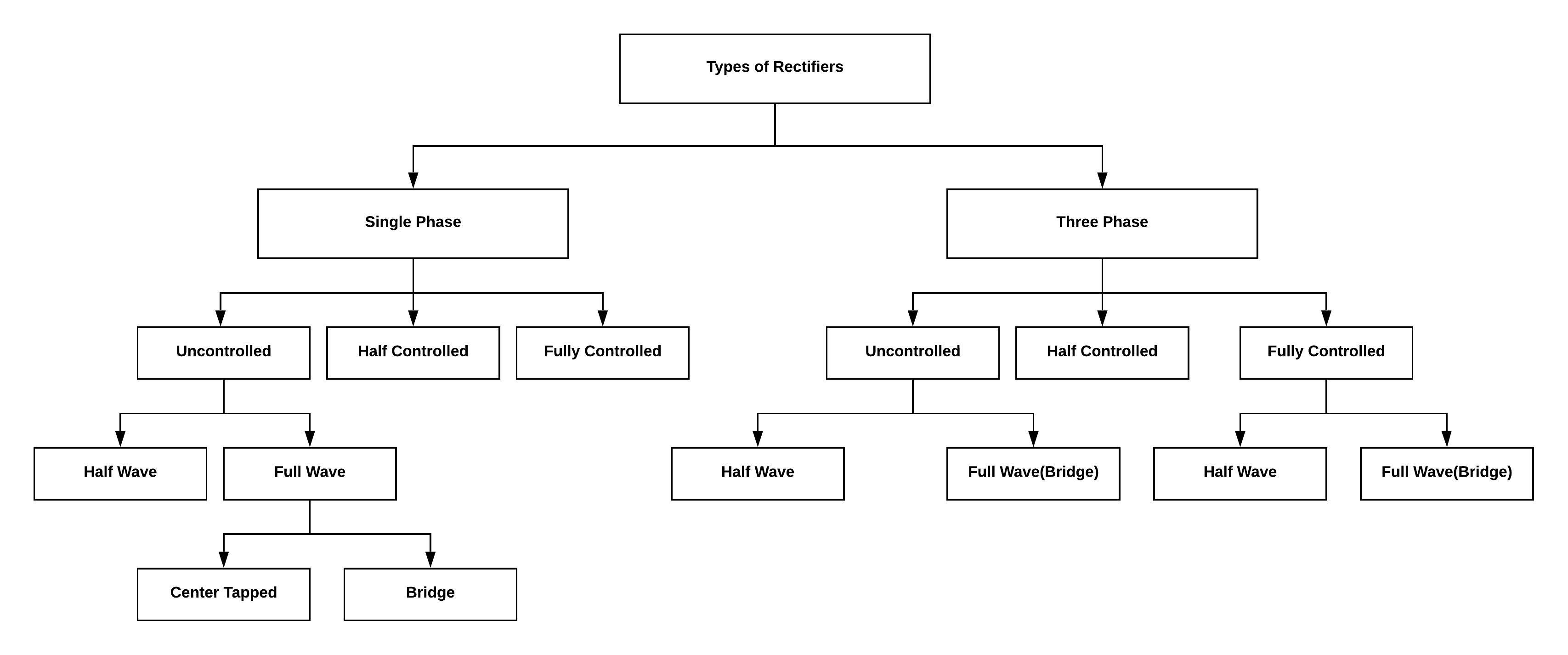
In this article, the initial types of rectifiers are classified as single phase and three phases. These rectifiers are further classified into controllable and uncontrollable rectifiers. Further classification of half wave and full wave rectifiers is overviewed with the help of a diagram. Full wave rectifiers based on the diodes used connected with center tap transformer where two diodes are preferred for rectification. The other type of full wave rectifier is where the four diodes are preferred for rectification connected in the bridge topology.
These classifications are overviewed in the below article. There are different properties related to the rectifiers based on which these types are compared. This also clearly tabulated in the below article. Once the rectifiers are described its factor can easily be described and its comparison is done. The comparison is done briefly so that one can choose a suitable rectifier based on its requirement.
Different Types of Rectifiers
There are certain factors like supply provided that can be either of positive value or negative, presence of essential components and the type of configuration used, based on which the types of rectifiers are classified. Hence these come under the category of the properties of the rectifiers. Based on the number of diodes present in the circuit give rise to the initial classification of the rectifier as:
(1) Single phase rectifier
(2) Three phase rectifier
Single Phase Rectifiers
If the rectifier consists of only one single diode for rectification it is referred to as single phase rectifiers. These rectifiers are further classified into uncontrolled, half controlled and fully controlled circuits. Uncontrolled single phase rectifiers again divided into half and full wave circuits where the full wave circuit is classified as center-tapped or bridge rectifiers.
Three Phase Rectifiers
In three-phase, there is three number of diodes present in the circuit in order to complete the process of rectification. Like-wise single phase it also classified as uncontrolled, half controlled and fully controlled circuits. Whereas uncontrolled and fully controlled are classified as half wave and full bridge rectifiers.
The only difference between the controlled and the uncontrolled rectifiers is that in the controlled rectifiers the output is controllable whereas in the uncontrolled rectifiers the output is not in control. In this case instead of using normal p-n junction diode, in the controlled rectifiers the silicon controlled rectifiers are used rest of the process will be similar to that of uncontrolled rectifiers.
Please refer to this link to know more about Silicon Controlled Rectifier MCQs
The silicon controlled rectifiers consist of three terminals. Like diode, it has anode and cathode but the most important terminal here is the third terminal known as a gate. The purpose of the gate is to control the output.

Half-Wave Rectifiers
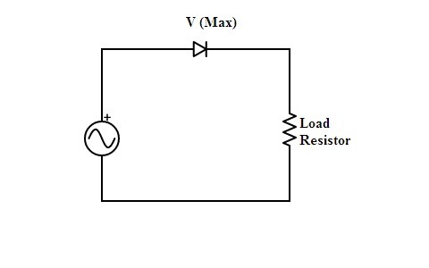
The AC is provided as the supply unit to the circuit. The diode is connected in series with the load resistor. In the single phase circuit, there exists only one diode. In the three-phase circuit there exist three numbers of diodes. This is the only difference between single phase and three phase half-wave rectifiers.

The purpose of half –wave rectifier is to consider half of the cycle. In this way, it is further divided into two types
(1) Positive half wave rectifier
In this, the rectification process considers the positive half cycle of the alternating current (AC) and this positive half is only converted into direct current (DC).
(2) Negative half wave rectifier
In this, the negative half cycle of the alternating current undergoes rectification and converted into direct current.
In the half-wave, only half of the input signal gets interacted with the circuit because other half is not considered here based on the priority. Hence the output produced here requires more filtering.
Full-wave Rectifier:
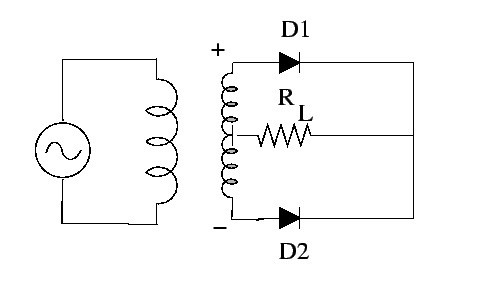
In this type rectifier, both the cycles of alternating current reaches the circuit and the direction of the flow of current at the load will be in the same direction it doesn’t get influenced whether it is negative half of the cycle or the positive half of the cycle at the input. In the circuit, there are two diodes. The two diodes purpose is one is conducted during the positive half and the other is during the negative half of the cycle.
Full wave rectifier is further classifies into two types
(1) Centre-Tapped Full Wave Rectifier
In this circuit of full wave rectifier transformed is used as the input supply unit where its secondary winding center is tapped. Hence the two diodes are present in the circuit one diode gets the input supply from the upper-half of the cycle other gets it from the negative half of the cycle. It indicates that both the cycles get utilized by the diodes. This results in an increase in the efficiency of the circuit.

(2) Full-wave Bridge Rectifier
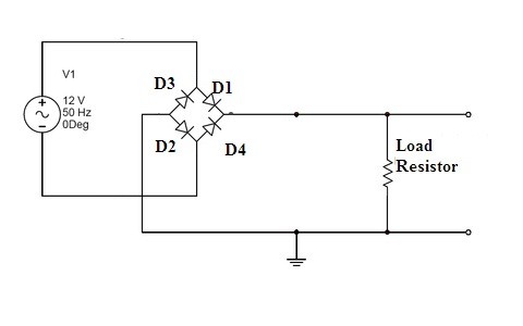
Instead of using center-tapped transformed here a normal transformer is considered here but in this rectifier, four diodes are connected in such a way that it follows bridge topology. Hence it is termed as a full-wave bridge rectifier. In this, the ac supply rectification is carried out diagonally. The load resistor is connected at the different ends of the diagonals.
 As the positive part of the AC, supply is provided diode D1 and D2 acts like they follow forward bias condition and diode D3 and D4 remain in reverse bias condition. Similarly, when the negative part of the supply is provided the diode D1 and D2 will be in reverse bias and diode D3 and D4 will be in forward bias. In this way, the circuit responds for both positive and negative side of the AC supply.
Comparison of Different Types of Rectifiers
The various types of rectifiers include a half-wave rectifier, full-wave based on center tapped and bridge concept. These rectifiers are compared based on its number of diodes present in the circuitry. Various factors lie ripple current, RMS current, maximum efficiency of the rectifier, average current value are the properties based on which rectifier’s comparison table has been drawn.
|
Properties of Rectifier |
Half-wave Rectifier |
Full-Wave (Center-Tapped) Rectifier |
Full-Wave(Bridge) Rectifier |
|
Number of diodes present in the circuitry |
1 |
2 |
4 |
|
Is the transformer required? |
No |
Yes |
No |
|
DC average |
I_m/π | 〖2I〗_m/π | 〖2I〗_m/π |
|
Maximum current value |
V_m/(r_f+R_L ) | V_m/(r_f+R_L ) | V_m/(2r_f+R_L ) |
|
Ripple Factor |
1.21 |
0.482 |
0.482 |
|
Maximum Efficiency |
40.6% |
81.2% |
81.2% |
|
Peak Inverse Voltage |
V_m | 〖2V〗_m | 〖2V〗_m |
|
Ripple Frequency |
50Hz |
100Hz |
100Hz |
|
Output Frequency |
f_in | 〖2f〗_in | 〖2f〗_in |
|
T.U.F |
0.287 |
0.693 |
0.812 |
The majority of electronic appliances require DC voltages as its source. The conversion of AC to DC is done with the help of basic electronic device referred to as the p-n junction diode. During its forward bias, the diode conducts and reverse bias the diode doesn’t conduct indicating the unique flow for the direction of the current. This is the reason p-n junction diode is suitable for rectification. Based on these rectifiers are classified.
The output obtained from the half-wave rectifier rectifies only either positive cycles or negative cycles. Hence its output consists of ripples. In order to overcome this ripples problem capacitor around the resistor must be placed. However, half of the AC supply remains unused in this type of rectifiers. Because of these reasons practical implementation of these circuits practically is not possible.
This reason paved the way for the introduction of full wave rectifiers. In the first case of full wave rectifier, it is center tapped where two diodes are considered. In the second full wave, the rectifier is designed with four diodes using bridge topology. It has the capacity of producing double output voltage value comparable to that of half wave rectifier. These p-n junction diode rectifiers come under uncontrolled rectifiers where silicon controlled rectifiers come under controlled rectifiers.
Please refer to this link to know more about Bridge Rectifier MCQs.
Please refer to this link to know more about Rectifiers MCQs
However, the consideration of controlled or uncontrolled single phase or three phases is completely based on its requirement. Even half wave rectifiers with certain modifications are preferred in some electronic modules. What will be the most used household thing where you prefer the concept of half wave rectifier?