A basic semiconductor, in that there is the presence of two terminals in which one is preferred as a cathode and the other as an anode. It is formed by the two different materials referred to as p-type and n-type. Generally, it is termed as p-n junction diode. As it is application-oriented it is also referred to as rectifier diode. The main purpose of this p-n junction diode is that it is used for the conversion of the applied alternating current (AC) into direct current (DC). This process of conversion is termed as rectification. This can be used as the basic module in the power supply unit in any electronic appliances where DC is considered for powering up the device.
What is a Rectifier Diode?
A rectifier diode is a basic semiconductor device which is used in various applications but one of its applications includes the conversion of power that is from low currents into high currents generally referred to as rectification.
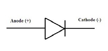
symbol of diode
The basic symbol of a diode that consists of both anode and cathode in it is sufficient enough to represent it as a diode. The alignment of this diode can be done in such a way that it becomes application-oriented. In general terms, it can work as a rectifier. The structure of the arrowhead in the above representation indicated the flow of the conventional current.
Rectifier Diode Circuit Working
A diode with its two basic terminals that are formed by the doping of p-type and n-type material on a single crystal has the presence of some inbuilt potential in it. If the diode is provided with some external voltage then the diode is said to be biased. This biasing is further classified as forward and reverse based on the application of external voltage to the respective terminals.
1). Unbiased Rectifier Diode
- A device or component without any external supply provide to it is referred as to be in unbiased mode or condition.
- Once a rectifier diode is considered it has some inbuilt potential in it even though there is an absence of external supply in it.
- As it has two partitions in it one side it has p-type and another side it has n-type material in it. There exists the concept of majority and minority carriers in it. In n-type electrons will come under the majority of the charge carriers and holes in the minority.
- Coming to p-type holes will be in majority and electrons will be in minority. Hence in n-type, the majority is of electrons so the free electrons in it tend to move towards p-side and the process of recombination takes place resulting in diffusion.
- Because of this, the immobile ions gets deposited across the junction. This deposition leads in the formation of the depletion region.
- This region is also referred to as barrier. In which there exists some barrier potential that avoids further movement in the charge carriers from one side to another.
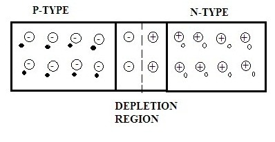
Unbiased-Rectifier Diode
(2) Forward Biased Diode
This condition in the diode can be due to the biasing. If the positive side of the supply is connected to the p-type of the diode terminal and the negative side of the supply provided is connected to the n-type of the diode terminal results in the forward bias condition.
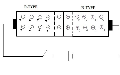
forward bias
- When positive supply is provided to the p-type and negative supply to the n-type the majority carriers tends to repel each other because the polarity of the voltage and charge on the majority carriers is similar. Hence the process of drift occurs.
- Once the electrons in n-type tend to drift there is the generation of drift current. Hence in n-type, the current is due to electrons and in p-type it is due to holes. So drift current is due to the drifting of the majority carriers.
- This type of current is referred to as forward current and the direction will be from the positive terminal to the negative terminal of the source and opposite to the direction of the flow of electrons.
(3) Reverse Biased Diode
If the biasing done in such a way that the positive side of the supply connected to the n-type terminal of the diode and the negative side of the supply connected to the p-type terminal of the diode results in reverse bias.
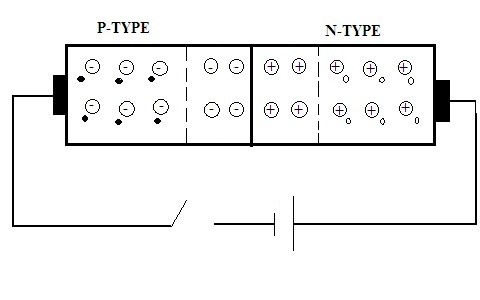
Reverse Bias
- As per the connections of the diode in reverse bias, there is no forward current evident here except the reverse saturation current.
- As there is the presence of depletion region but its width tends to increase. However, there is no flow can be seen in majority carriers but due to minority carrier’s effect, some current is generated referred to as reverse saturation current.
- If the reverse saturation current tends to increase in the diode then a point comes where the width of the depletion region is completely eliminated resulting in a large amount of flow of reverse current in the diode resulting in the breakdown of the diode.
Applications
Few applications of the diode are listed below as follows
- It is used in the rectifier circuit as the basic block of rectification.
- It is used in clamping circuits and the purpose behind this is to work as level shifter or to restore DC.
- It is used in the designing of logic gates in order to perform digital operations.
- It is applicable in the voltage multipliers.
- In order to provide protection to the solar panels, other types of diodes are preferably used.
- During the suppression of spikes in voltage, the diodes are applicable.
- LASER is also one of the applications of the diode.
- Detection and mixing of the signals are also can be done by the diode.
Let us discuss the important application of the diode that is rectifier. These rectifiers based on the diodes used are classified into various types.
Half Wave Diode Rectifier
In this, a single diode is used it is connected in series with the load and the supply. This is the basic diode rectifier that utilized only a single cycle either positive or negative for rectification.
For positive half of the cycle, the diode will be in forward bias that is in conducting mode. For the negative half, it will be in reverse bias that is in the blocking stage as per the property of diode.
However, there will be a loss of power due to this. This kind of circuit is not suitable for practical applications because its ripple factor will be high leads to low circuit efficiency.
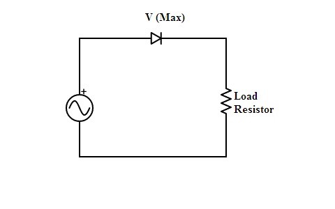
half wave rectifier
Full Wave Diode Rectifier
In this type of rectifier, more than one diode is utilized during rectification. In half-wave rectifier, there is the loss of power due to the usage of only one cycle in order to overcome this problem full-wave rectifier is designed. It utilizes both the cycles for the rectification. Further, it is classified into two types
1). Center Tapped
In this a transformer that has a wire in the secondary winding at the center it is used along with two diodes and followed by a resistive load.
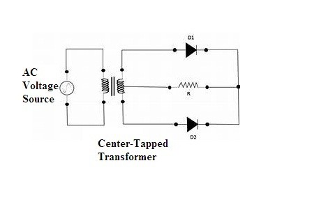
Full Wave Rectifier (Center-Tapped)
For the positive cycle, D1 conducts and for the negative cycle D2 conducts. However, both the cycles are utilized and the loss of power is minimized and also the ripple factor by increasing efficiency of the circuit. The only drawback is that the transformer utilized here is costly enough.
2). Diode Bridge Rectifier
As the center-tapped transformer making the circuit costly a rectifier with four diodes connected in the bridge topology is designed.
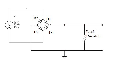
full-wave rectifier (bridge)
Once the circuit is provided with the sufficient supply for the positive duration of the cycle D1 and D2 will be in forward bias and the path has been established for the flow of current. Whereas D3 and D4 will remain in reverse bias condition.
For the negative half of the cycle, D3 and D4 will be in conduction mode whereas D1 and D2 in the blocked state. Hence both the cycles are utilized in this process making circuit efficient enough.
Compared to the center-tapped, a diode bridge rectifier is of less cost. It is simple to analyze and consists of minimum ripple factor value providing maximum efficiency comparable to that of a half-wave rectifier.
However, the output generated consists of ripples in it indicating that the output is not in its purest form. For the effect of smoothening of the output generated capacitors are connected across the load so that they can function as filters.
Please refer to this link to know more about Rectifiers MCQs & Bridge Rectifier MCQs.
Please refer to this link for Choosing resistor values for diodes.
Hence the part of rectification is completely dependent on the component used referred to a diode. Based on the number of diodes required cycles rectification can take place. Because of the biasing conditions of the diode, it is suitable in various applications. As per the above realizations is there any existence of current when the diode is in unbiased mode?