In electronics and electrical engineering, many network theorems are used to solve complex and multi-loop circuits. The network theorem is used in the analysis of AC networks. They are classified into various types such as Thevenin’s theorem, Superposition theorem, Norton’s theorem, maximum power transfer theorem, Millman’s theorem, Substitution theorem, and reciprocity theorem. This article describes the reciprocity theorem, which is used in both circuit theory and field theory.
Since the analysis of circuits is done by using Kirchhoff’s laws and Ohm’s, which leads to long system equations and it is difficult to determine the particular unknown components like the voltage, current, resistance in the circuit. Hence to determine the particular source and response of the entire network/circuit, the network theorems are utilized, which requires simple mathematics for analysis and to find the solution.
What is Reciprocity Theorem?
In any electrical circuit, if the positions of the ammeter and the voltage source are interchanged, then there would be no change in the output reading of the ammeter. For example, consider a voltage source connected to a passive electrical circuit and the output response can be obtained by connecting the ammeter to another part of the circuit.
If the positions of the voltage source and ammeter are interchanged, then the output response indicated by the ammeter remains the same in both cases. That means, the reciprocity property exists in the circuit and it is called the reciprocity circuit that obeys the reciprocity theorem. The output response of the ammeter indicates the current flowing through the circuit. In special cases, it is referred to as Rayleigh Carson reciprocity, which was named after the work done by Hendrik Lorentz in 1896. This theorem is applicable for only single-source networks, not multi-source networks.
State Reciprocity Theorem
The reciprocity theorem states that in any branch of the electrical circuit or network the value of current obtained due to the single voltage source (V) in the circuit/network is the same as the value of current flowing through that branch, in which the source was originally connected and when the source was again connected to the branch in which the value of current was originally determined.
This reciprocity theorem statement is employed in linear and bilateral networks, in which the circuit consists of only one independent source. It is used for both DC and AC circuits. In other words, the reciprocity theorem statement is nothing but, when the positions of the voltage and current sources of any network are interchanged, then the same or equal magnitude or amount of voltage and current flows through the network or circuit.
Lorentz Reciprocity Theorem
Lorentz reciprocity theorem states that the oscillating current and resultant electric field remain constant even when the positions of current and the measurement of the electric field are interchanged. This theorem gives the relationship between one distribution current and the resultant electric fields, and a second distribution current and the resultant electric fields when they both criteria take place in similar regions of space filled with a similar distribution of linear matter.
Circuit Theory
The procedure required to solve the circuit/network using the reciprocity theorem is given below.
- Select the branches of the circuit, where the reciprocity theorem circuit/network theory has to be applied
- Obtain the flow of current using any one of the network analysis techniques.
- Interchange voltage source of the selected branch.
- Obtain the value of current after interchanging the voltage source.
- Now observe that the value of current obtained before and after an interchange of the voltage source is identical.
- Hence the verification of the reciprocity theorem is done.
Verification
The verification of the reciprocity theorem is explained from the circuit diagram shown below. From the circuit, the position of the current source and the voltage source are interchanged without a change in current. Since the polarities of the voltage source and the branch current direction are identical. To solve the given circuit, the voltage source and the current source are interested in utilizing the reciprocity theorem.
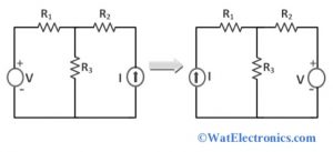
Verification of Reciprocity Theorem
To solve the circuit or network with the help of the reciprocity theorem, the circuit must be linear with connected resistors, inductors, capacitors, and coupled circuits. The circuit with reciprocity property doesn’t contain any time-varying components. The internal resistance of the voltage source and the current source is zero because they are ideal.
Experiment
In the reciprocity theorem, experiment, in any linear and bilateral network, the impedance (ratio of the applied voltage between the two terminals and current measured in the branch) in any branch is identical to the ratio of voltage (V) to current (I) obtained by interchanging the positions of ammeter (for current measurement) and voltage source.
The ratio of voltage to current is called transfer impedance. The voltage source and ammeter must have zero impedance. Because the reciprocity theorem is applicable only when they have the same internal impedances.
Consider an antenna system with the 4-terminal network, which consists of one pair of input terminals and another pair of output terminals as shown in the figure below. It is also referred to as 2- port network.
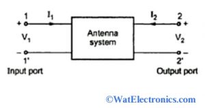
2-Port Antenna System
Here,
V1 = Z11. I1 + Z12. I2
V2 = Z21. I1 + Z22. I2
Similarly,
I1 = Y11. V1 + Y12. V2
I2 = Y21. V1 + Y22. V2
According to the reciprocity theorem in linear and bilateral networks, the reciprocity conditions of the given network are,
Z12 = Z21 or Y12 = Y21 or Z12′ = Z21′
Where Z12 and Z21 are the mutual impedances, which are individual ratios of open circuit Voltage at one terminal and the measured current at another terminal.
Y12 and Y21 are transfer admittances, which are individual ratios of short circuit current at one terminal to the voltage at another terminal.
Z12′ and Z21′ are the transfer impedances, which are individual ratios of open-circuit voltage and short circuit current.
Proof: consider the network given below to find the response I2 with a voltage source E.
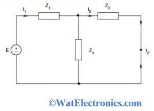
Case 1
Case 1: Form the circuit,
Zeff = (Z2 || Z3) + Z1
Zeff= (Z2.Z3 / Z2 + Z3) + Z3
Zeff= (Z2. Z3 + Z1. Z2 + Z3. Z1) / (Z2 + Z3)
I1= E / Zeff
Therefore I2 = I1.[ Z3 /(Z1 + Z3) ]
I2 = EZ3 / (Z1.Z2 + Z2. Z3 + Z3. Z1)
Case 2: Consider the network is shown below, where the positions of the voltage source and the output response I of the network interchanged.
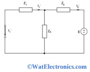
Case 2
From the figure,
Zeff = (Z1 || Z3) / Z2
= (Z1.Z2 + Z2.Z3 + Z3.Z1) / (Z1 + Z3)
I2′ = E / Zeff
I1′ = I2′ [ Z3 /(Z1 + Z3)]
I1′ = EZ3 / (Z1.Z2 + Z2. Z3 + Z3. Z1)
From the above reciprocity theorem experiment, it is proved that the response I of the network is the same as before and after interchanged positions of the voltage source and current source. Hence the verification of the reciprocity theorem is done.
Theorem in Antenna
The reciprocity theorem in an antenna is one of the properties. It states that the transmit and receive properties of antennas are similar. That means the radiation pattern of transmit antenna and receive antenna are the same.
When the antenna is used as both receiving antenna and transmitting antenna, the properties might change due to the change in operating mode. But the antenna properties are unchanged due to the reciprocity property.
Reciprocity theorem is widely used in transmitting antenna and receiving antenna to derive various properties like,
Equality of Directional Patterns
When the transmitting antenna transmits the signals to the receiving antenna, the radiation patterns of both antennas will be equal.
Equality of Directivities
The transmitting antenna and receiving antenna will have the same directivity. Hence, the value of directivity can be calculated from either power of receiving antenna or the transmitting antenna.
Equality of Effective Lengths
The maximum effective aperture value will be the same for the transmitting antenna and receiving antenna. The equality in the length of transmitting and receiving antennas depends on the wavelength value.
Equality of Antenna Impedances
In communication, the output impedance of the transmitting antenna is equal to the input impedance of the receiving antenna.
These properties don’t change even though the antenna is operated in either receive mode or transmit mode. Hence the reciprocity theorem in antennas is applicable.
Application of Reciprocity Theorem in Antenna
According to the antenna theorem, the application of the reciprocity theorem is used in both bilateral and linear networks. The reciprocity theorem is applicable to derive all the properties of antennas mentioned in the above section. Now one of the properties of antennas with reciprocity property is explained below.
Equality in directional patterns: the directional patterns of both the transmitting antenna and receiving antenna are identical. This statement shows that the reciprocity theorem in the antenna is applicable.
The transmitting antenna’s directional pattern is represented with polar characteristics (amplitude and direction) because the strength of the radiated field is indicated at a fixed distance in various directions in the space. Since the strength of the antenna indicates amplitude. Similarly, the receiving antenna’s directional pattern is represented as polar characteristics. The response of the antenna from different directions for unit field strength is indicated by the receiving antenna.
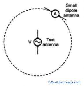
When the antenna is operated as a transmitting antenna, its directional pattern is measured by placing the test antenna at the center of the sphere. The small dipole antenna is also considered during the measurement, and it is moved along the surface of the sphere as shown in the figure below.
Application of Reciprocity Theorem in Antenna
A voltage source V is connected to the test antenna and the current flowing in the dipole antenna at different positions is measured using an ammeter. The current in the dipole antenna is nothing but the electric field at different positions. Observe the pattern of the transmitting antenna (test antenna). Now with the application of reciprocity theorem in antenna, interchange the positions of voltage V and the current measurement.
That means the voltage V is connected to the terminals of the dipole antenna and it is moved along with the surface of the sphere to different positions. To measure the current flow, the ammeter is connected to the test antenna, which is placed at the center of the sphere. Hence the pattern received by the test antenna can be obtained.
According to the reciprocity theorem in the antenna, for every position of the dipole antenna, the voltage (V) to current (I) ratio is the same as before, which is equal to the value obtained in the test antenna as the transmitting antenna. Therefore it is proved that on the application of reciprocity theorem in antenna, the radiation pattern or directional pattern of a transmitting antenna is identical to that of the receiving antenna.
When linear polarization is considered instead of circular polarization, the orientation of the dipole antenna is in such a way that is parallel to the electric vector and perpendicular to the radius vector.
Know more about DeMorgan’s Theorem.
Thus, this is all about an overview of reciprocity theorem – statement, reciprocity theorem circuit theory, reciprocity theorem in antenna, reciprocity theorem experiment, verification of reciprocity theorem, and application of reciprocity theorem in antenna. This theorem is used in both circuit theory and field theory. Here is a question for you, “What are the applications of reciprocity theorem in circuit theory?”