A Capacitor is an electrical component, which is used to store electric charges temporarily. The unit of a capacitor is the farad (F). A Power Capacitor is a special type of capacitor, which can operate at higher voltages and has high capacitances. This article gives you a brief introduction to a power capacitor and its working principle, formula, connection, types of applications, and more. Want to learn more about capacitor and how it works? Read our article: Capacitor Working & Its Applications.
What is a Power Capacitor?/Definition
A Power Capacitor is an electrical device that can store and discharge electric energy. The device consists of one or more pairs of plates, separated by an insulating material (the dielectric), which are attached to two terminals that allow the stored energy to be discharged into a circuit when required. The power capacitor symbol is shown below.

Power Capacitor Symbol
Power capacitors are used to defend different types of equipment from resonance and to develop power quality through absorbing harmonic currents, generated by induction load. These capacitors are available with higher values above 1 Farad. So these can be used in place of a chemical battery.
Power capacitors play a key role in providing an inactive reactive power source within electrical distribution systems. They include two conducting plates which are separated through an insulating material known as a dielectric. The capacitance of a power capacitor is a measure of energy storage capacity that is normally expressed as
C = K*A/D
Where,
‘A’ is the area of the electrode,
‘D’ is their separation
‘K’ is the dielectric function between the two electrodes.
Construction
The construction of a power capacitor can be done with various smaller capacitors which are known as packs or windings or elements. These smaller capacitors can be formed with different aluminum foil & polypropylene film layers. Once various capacitors are interconnected then these capacitors can combine to work as a single capacitor unit.
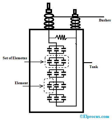
Power Capacitor Construction
The connection of different elements can be done in series depending on rated voltage and also in parallel depending on necessary kvar. The whole module can be arranged in a tank which is sealed hermetically & the air in the unit can be removed by replacing it through a dielectric fluid. The units of this capacitor include bushings on the top with terminal caps which works as connection points.
Power capacitors within distribution systems provide reactive power to equalize inductive loading from motors, lighting loads, and arc furnaces. The inclusion of power capacitors into a power distribution system provides operational & economical benefits like enhancing the load capacity of a system, enhancing power factor & decreasing losses.
How do they work? / Working Principle
Power capacitors have two plates inside of them that are coated with a material that allows them to store an electric charge. When the capacitor is connected in parallel to an inductive load, it will start to charge when the voltage rises above the current level of the load. The difference between the voltage and current levels is called a phase angle. This angle determines how much energy will be stored in the device by the time it is fully charged. The more energy that’s stored, the faster it can discharge into another load.
Specifications
The specifications of a power capacitor mainly include WVDC (working DC voltage), WVAC (working AC voltage), power rating, rated current, temperature coefficient, insulation resistance, and dissipation factor and each specification is discussed below.
- WVAC & WVDC are the maximum AC & DC voltages that can be constantly used at any temperature which ranges from a low category temperature to the rated temperature.
The maximum power which is used constantly across the same temperature intervals is known as power rating. - The maximum current is known as rated current.
- The change within measured capacitance over a temperature range is called the temperature coefficient.
- Insulation resistance can be defined as the ratio between an applied DC voltage & the resultant leakage current.
- The dissipation factor or DF is the ratio in between both the resistive & reactive parts of an impedance of capacitor once a sinusoidal voltage is applied at a fixed frequency.
Features
The features of a power capacitor include the following.
- Power capacitors use radial, axial, tab, flying, screw, J-leads, or gull wing.
- The SMT or Surface mount technology and THT or Through-hole technology-based power capacitors are connected onto a PCB (PCB) by placing the leads of components throughout holes and after that components, leads are soldered on the opposite face of the PCB.
- These types of capacitors are packaged within trays, rails or tape reels, stick magazines, or shipping tubes within bulk packs.
- Power capacitors including leads on four faces are packed frequently in rails or trays that are designed with fiber materials or carbon powder and shaped into a rectangular shape that includes equally spaced pocket matrices.
Power Capacitor Types
Power capacitors are available in different types based on its requirement like series, parallel, circuit breaker, coupling, electric, pulse, DC filter, and standard capacitor. Please refer to this link to know more about: Types of Capacitors
Parallel Capacitors
Parallel capacitors or phase shift capacitors are generally used to compensate for the inductive load’s reactive power within the power system so that the power factor can be increased, line loss can be decreased and voltage quality can be enhanced.
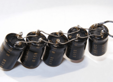
Parallel Capacitors
Series Capacitors
Series capacitors are used in high voltage systems to compensate for the power systems’ reactance. The connection of these capacitors can be done in series with high voltage transmission & distribution lines to compensate for the inductive reactance of the transmission line and also to maintain the stable & dynamic system stability.
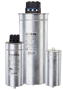
Series Capacitors
So this capacitor is very helpful in enhancing the voltage quality of the transmission line, the distance of power transmission can be improved & transmission capacity also increased.
Coupling Capacitors
These capacitors are used in high-power transmission lines for control, measurement, high-frequency communication, and protection. These capacitors play a key role in devices to remove electric energy.
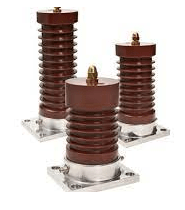
Coupling Capacitors
Electric Capacitors
These capacitors play a major role in electric heating systems with 40 to 24000 Hz frequency range to enhance the power factor and the frequency or voltage of the circuit.
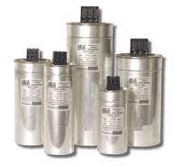
Electric Capacitors
Pulse Capacitors
These are polypropylene film capacitors and these are used where stable low dissipation factors are necessary to handle ripple currents within power conversion-based applications. These capacitors can be used as energy storage components like inrush current generators, impulse voltage generators, or in an oscillation circuit for a circuit breaker test.
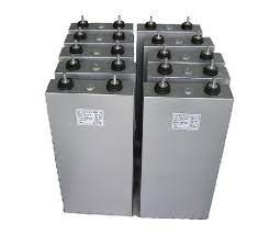
Pulse Capacitors
DC Filter Capacitors
These capacitors are applicable in high-voltage-based rectifier filters and DC devices.
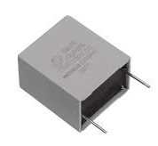
DC Filter Capacitor
Standard Capacitor
Standard capacitors are used in the high-voltage-based circuits to measure high voltage & dielectric loss.
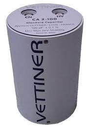
Standard Capacitor
Power Capacitor Connection:
The power capacitor can be connected in single-phase and three-phase connections which are discussed below.
Single-phase Power Capacitor Connection
In a single-phase system, the capacitor is connected in series with the start winding of the compressor motor. The capacitor is usually connected across the main supply, but it can also be connected across the start winding. Each method has its own advantages and disadvantages.
The most common method is to connect the capacitor across the L1 and L2 of the main supply. The capacitor value should be selected so that the total capacitive reactance equals roughly 5 to 10 times the inductive reactance of the compressor motor. This will ensure that there is sufficient capacitive current to get the motor started quickly and reliably. It will also ensure that there is adequate torque to overcome mechanical friction caused by tight bearings or low-viscosity oil.
When connecting a capacitor across L1 and L2, you must use a voltage-rated capacitor of at least 125% of the peak line voltage, which is 1.414 times RMS (root mean square) voltage. In other words, if you have a 120 VAC supply, you need at least a 150 VAC rated capacitor (1.25 x 120 V = 150 V).
Three-phase Power Capacitor Connection:
If the power capacitor is connected to the three-phase power supply, the power capacitor connection method is divided into two types: star and delta.
Star Connection
The star connection method is also called the Y connection method. The positive and negative electrodes of each phase of the power capacitor are connected to the neutral point of the three-phase line (U, V, W). This method can reduce the unbalanced capacitance current in the three-phase line, increase the voltage balance in each phase, and avoid saturation of the magnetic core in the low voltage side transformer; but the disadvantage is that it squanders a lot of energy in the neutral point.
Therefore, this method is only used when there is a significant difference between positive sequence and negative sequence currents.
Delta Connection
The delta connection method is also called triangle connection. The positive and negative electrodes of each phase of the power capacitor are connected to two phases of any phase respectively (for example U1, U2).
This method can effectively improve the voltage balance between lines, but it causes an imbalance of reactive power consumption on each line because it does not cause an imbalance between positive and negative sequences. Therefore, this method should be used when there is no significant difference between positive sequence and negative sequence currents.
Power Capacitor Selection Criteria:
While the concept of a power capacitor may sound simple, there are many different models on the market that come with different benefits. The three major factors to consider are voltage rating, capacitance, and frequency rating. Here’s what you need to know about each of these aspects:
Voltage Rating
The voltage rating of your power capacitor is determined by its dielectric material. Some dielectrics can withstand very high voltages; others cannot. Be sure to choose one that will work for your application.
Capacitance
Power capacitors come in many different sizes and shapes; however, their main function remains the same: storing electrical energy. The larger the capacitor, the more charge it can hold, which means more power will be available at any given moment when it’s needed most.
Frequency Rating
Some power capacitors are designed specifically for low-frequency applications and some are designed for high-frequency applications (for example, in audio amplifiers).
Power Capacitor Advantages and Disadvantages
Power capacitors are great for improving power factors, reducing energy costs, preventing voltage flickers, and more! Learn about the advantages and disadvantages of using power caps in your system today.
The advantages of a power capacitor include the following.
- Lower utility bills. Because you will be drawing less energy from the grid, your energy bill will decrease.
- Voltage stabilization. Power capacitors help balance the voltage on your site, so you won’t need to worry about unstable voltage causing problems at your business or facility.
- Charge and discharge much more quickly than batteries, which means they can provide bursts of energy when needed.
- Charge cycles – They aren’t worn down by repeated charging and discharging, like batteries.
- It requires little maintenance or upkeep, since it has no moving parts.
- It’s compact and lightweight, making it easy to install in any number of settings.
The disadvantages of a power capacitor include the following.
- Power capacitor drawbacks include a cost that is significantly higher than other types of capacitors.
- Power capacitors are only able to work in applications that have been rated for their frequency and voltage.
- They have the disadvantage of being susceptible to dielectric absorption, which can be an issue in some applications, though this particular problem can be corrected with proper design.
- Prone to ageing with exposure to high voltages and high frequencies, which can lead to failure over time.
- Sensitive to moisture and can easily be damaged by water or high humidity.
- They need insulation from the heat that is produced during the process of working. The insulation layer can get damaged, which leads to overheating and breakdown at a faster pace.
Power Capacitor Applications/Uses:
Here are some of the most common uses of power capacitors:
- Power Factor Correction (PFC) – Power factor correction is used for improving the efficiency of electrical equipment by reducing the amount of current that needs to be drawn from the main supply for a given level of output.
- DC Link Capacitors.
- Frequency Converters.
- Motor Start and DC Link Capacitors.
- In harmonics filter circuits.
- They are also used in a variety of applications like air conditioners, refrigerators, elevators, fans, motors, etc.
- Power capacitors also contribute to quality power consumption by reducing losses from reactive power consumption.
- Power capacitors are also used in energy storage applications such as those found in electric vehicles (EVs) and hybrid electric vehicles (HEVs).
What is the Purpose of Power Capacitor?
A power capacitor is a device used to store electric energy in an electric field or electrostatic field. It is similar to a battery but works on the principle of capacitance. It has two conducting plates which are separated by a dielectric. The dielectric can be either solid, liquid or gas material.
When Should You Use a Power Capacitor?
In the world of electronics, a capacitor is a device designed to store an electric charge. When it comes to power capacitors, are specifically used to smooth out the flow of electricity in an electrical system. As you may have heard, electricity can be unpredictable and can cause fluctuations that harm other electrical systems in the area. Power capacitors are designed to correct this problem and ensure that the electricity flowing through your system remains smooth, consistent, and safe.
What is the Average Power a Power Capacitor draws?
The average power a power capacitor draws is a function of the size of the capacitor, and what circuit it is attached to. For example, a 400-volt capacitor rated at 25 microfarads will draw approximately 0.8 amps of current when attached to a circuit with an operating frequency of 50 Hertz (cycles per second).
Why does a Circuit Need a Power Capacitor?
When electrical current flows through an AC system like an air conditioner or refrigerator, there will be fluctuations in the flow of current, which can cause damage to the electrical components. The resistance of these components can increase when they are exposed to these fluctuations, causing them to produce heat and eventually fail. A power capacitor helps protect against this problem by regulating the flow of current in order to minimize those fluctuations.
How is it Different than a Power Bank?
A power bank is a portable battery that stores energy for future use. They are typically found in smartphones, laptops, tablets, etc. Power banks are similar to power capacitors in that they store energy for later use, but they do not provide as much power or last as long as a capacitor.
How Often Should I Replace My Power Capacitor?
Most capacitors are rated for a certain lifespan and have the number of ‘equivalent operating hours’ (or EOH) they can be expected to work printed on them. This is a measure of how many hours the capacitor can be used at full capacity before it begins to wear out—once it reaches its maximum EOH, you should begin replacing it as soon as possible.
What are some other names of a Power Capacitor?
There are many different names that a Power Capacitor can be referred to. Some of these names include an energy storage capacitor, energy capacitor, power bank, flash capacitor, battery capacitor, supercapacitor, ultracapacitor, or charge-storage capacitor.
Please refer to this link to know more about Super Capacitor, Paper Capacitor , Variable Capacitor.
know more about Parallel Plate Capacitor MCQs, PCB Design MCQs.
Thus, this is all about brief information on a power capacitor. There are some precautions that must be taken while installing power capacitors; these capacitors must be connected where there is no vibration, corrosive gas, explosion, impact, flammability, etc. Here is a question for you, what is a capacitor bank?