Sensors are the devices or modules or subsystems that detects and collects the data from the changes in physical parameter or environment and provides the electrical information to the systems to transmission systems, measurement systems, processors, electronics, medical equipment, etc. Among the various sensors, the position sensors are most widely used in different applications with different technologies and sensing principles. With the improving technology, the position sensors are available in small sizes, and various designs at low cost with good performance. This article gives a brief description of the working, types, and interfacing of a position sensor.
What is a Position Sensor?
The sensor that is used to monitor and detect the movement or relative position of a target/object or obstacle from the fixed reference point is called a position sensor. It is used to measure the distance between the reference point and the present location of the object. They can detect the presence or absence of an object and provides position information like speed, distance, motion, direction, etc.
To indicate the position of an object and to find the interruptions due to electrical and magnetic fields, it monitors, detects, and converts the physical parameters into an electrical output signal. These are available in linear type and rotary type sensors because they can detect the rotational/angular Or linear movement of the object.
It provides a signal that changes depending on the position of the object. This movement is converted into a displacement. The path or displacement and position of the object are determined by counting the transmitted pulses. For example, it can give a signal through the field in the absence of a mechanical connection between the field and the moving object. These can be electromagnetic fields as in eddy current sensors or magnetic induction fields as in hall effect sensors or electrostatic fields as in capacitive sensors.
A few examples of applications by using position sensors are given below.
> Labelling control
> Control Printing process
> Steering systems
> Oncology and MRI machines
> Nuclear plants
> Machine builders
> Structural testing
> Automotive testing
> Elevators
> Bridge movement and many more.
Position Sensor Working Principle
The working principle and construction of the position sensor are based on the type of technology used, the type of measurement, and the method used for generating the output signal. There are several types of position sensors, which are discussed below. Now, consider a basic position sensor type called potentiometric position sensor to understand the working principle easily.
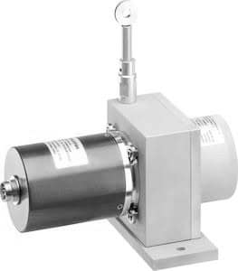
Potentiometric Position Sensor
The potentiometric position sensors most widely used sensors because they are easy to use and available at a low cost. These can be used as either linear or rotational position sensors. The potentiometric position sensor construction is shown below.
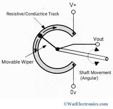
Potentiometric Position Sensor Construction
These sensors are also known as potentiometers and contain a resistive sensing element used to detect the position of an object. It consists of a fixed terminal and wiper attached to a mechanical shaft for the movement along the track that is either linear or angular type. The wiper with a resistive tract is connected to an object to detect and monitor the object’s position.
As the object moves, the position of the wiper changes position along the resistance (conductive) track, changing the resistance value between the position of the wiper and the end of the track. The resistance thus measured can be used as an indicator of the position of the object. This is achieved with a voltage divider where a fixed voltage is applied to the end of the resistor track and the voltage measured from the position of the wiper to one end of the track gives a resistance value proportional to the wiper position. This method applies to both linear and rotational movements of an object.
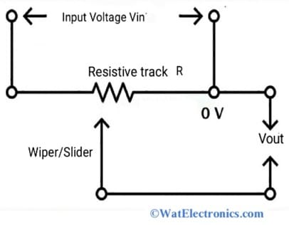
Resistance Measurement
The resistance that is measured between the fixed terminal and the other end of the wiper is proportional to the movement of the wiper. For example, when a 6V reference voltage is applied, the total output voltage will range from 0V to 6V. If the wiper is at the center position of the resistive track, then the output voltage will be 3V. Consider the simple circuit shown above to understand easily.
There are 3 types of potentiometers- wire wound type, plastic film type, and cermet type. The drawbacks of these sensors are low accuracy, limited frequency, low repeatability, and fraction due to moving parts.
Position Sensor Types
The position sensors are divided into several types based on application, technology type, and measurement. Position sensors are classified into two types based on the measurement like the following.
Linear Position Sensors
These are used in the measurement of linear movements such as up or down or side-to-side in a specific range. Based on the certain range of applications, the position sensor type is selected. These are used to determine the changes in the position of an object and calculate the distance between the object/obstacle and a reference point. It converts displacement into electrical output signals and is used in various industrial applications, scientific labs, etc.
Rotary or Angular position sensors
These are used to monitor/detect the moment of an object and convert the mechanical angular position of an object into an electrical signal. These are used in controlling the frequency, and speed in various applications. These are highly reliable and give measurements with high precision.
In linear and rotary position sensors, different technology types are used, which can be either non-contact or contact types. The basic position sensor types based on the type of technology used are given below.
Potentiometric Position Sensors
These are also known as position transducers or potentiometers or resistive position sensors used in military applications, as adjustment knobs in radios and TVs. These can be easily operated as rotary or linear position sensors and are available in various sizes and designs at low cost. Low accuracy, repeatability, and measurement range are determined by its design and size.
Inductive Position Sensors
These are non-contact proximity sensors used to detect the conducting object’s position (ferrous and non-ferrous targets) along with the changes in the magnetic field induced in the sensor’s coils. These provide better accuracy, good resolution, good linearity and high sensitivity. These are used in counting applications, security systems such as metal detectors, military applications to detect landmines, etc.
It is divided into 2 types. They are LVDT (Linear variable differential transformer) and RVDT (Rotary variable differential transformer).
LVDT is a linear type position sensor used to detect the linear moment of the object. While the RVDT is a rotary type position sensor used to detect the angular or rotational moment/position of the object.
Capacitive Position Sensors
These are non-contact position sensors used to detect the position of a conducting and non-conducting object based on the changes in capacitance. The object’s position can be detected with the help of 2 methods. They are, by changing the dielectric constant of a capacitor and by changing the overlapping area of the capacitor plates. These have low sensitivity, high resolution, high performance, high precision, high accuracy, and low-cost sensors used in industrial applications, semiconductor technology, disk drives, and linear displacement measurements (few mm to nm).
Eddy Current-based Position Sensors
These are non-contact position sensors that operate on the principle of magnetic induction to measure the displacement, position, vibration, and oscillation of a conductive object/target. These low-sensitive sensors provide high precision measurement and can tolerate harsh environmental conditions. Available at low cost and in smaller sizes. These sensors are rarely used in applications where the distance between the object/target and sensor is large and high resolution is required.
Magnetostrictive Position Sensors
These are non-contact linear position sensors used to detect the position of an object/target and are available with several outputs like current, PWM signals, DC voltage, and digital pulses. The ferromagnetic materials (iron, cobalt, nickel) have a magnetostrictive property. That means these materials change their size and shape due to the presence of magnetic fields.
Hall-Effect based Magnetic Position Sensors/Magnetic Position Sensors
These are non-contact position sensors used to detect the object’s position by monitoring the changes in direction and strength of magnetic fields generated due to electric current, from Earth, and magnets. These are used in navigation systems and industries. These are highly accurate, high-speed position sensors available at affordable rates.
These sensors work on the Hall-Effect principle, which states that when a current-carrying conductor is kept in a magnetic field, then the generated voltage is 90 degrees (perpendicular direction) to both the magnetic field and the current. These are available with both digital and analog outputs and operate at a range of -40°C-150°C temperature.
Optical Position Sensors
These are non-contact position sensors that work similarly to the photoresistors and determine the physical quantities like pressure, temperature, displacement, rotation, position, force, acceleration, magnetic, electric, and acoustic fields, radiation, pH values, velocity, strain, liquid level, and flow.
The measured physical quantities are translated into a readable format by an appropriate device. These sensors can provide high reliability, fast speed response, and high resolution. The most widely used optical sensors are position-sensitive detectors (PSDs) and encoder-based optical position sensors for linear and rotational measurements.
It converts the light signals into electrical signals by monitoring the changes in characteristics of light like intensity, wavelength, polarization, and phase to know information about the position of the object. It is divided into 3 types. They are transmissive optical encoders, reflective optical encoders, and Interferential optical encoders.
Fibre Optic Position Sensors
These are used to detect the strain, temperature, displacement, pressure, acceleration, and velocity by using an optical fiber as a sensing device. Used for sensing the position at longer distances. It provides high immunity to electromagnetic radiation, magnetic fields, and harsh environmental and lighting conditions. It consists of electrically insulating material and has the ability of multiplexing signals.
These sensors are divided into 2 types. They are intrinsic and extrinsic sensors.
Ultrasonic Sensors
Like optical sensors, ultrasonic sensors emit high-frequency sound waves, usually generated by a piezoelectric transducer. The ultrasonic waves generated by the transducer are reflected by the measurement object/target and the reflected signal is read by the transducer where an output signal is generated. Ultrasonic sensors can act as proximity sensors to report objects at a certain distance from the sensor, or as position sensors to provide distance information.
The advantages of these position sensors are, that they work with a variety of surface properties and materials of objects/targets and can detect small objects at greater distances than other types of position sensors. It is also resistant to ambient noise, vibration, electromagnetic interference, and infrared radiation.
Position Sensor Interfacing With Microcontroller
In this section, let’s learn how to interface a position sensor with a microcontroller. Here, a GPS receiver sensor module called (GY-GPS6MV2), which is one of the applications of position sensors, is considered for interfacing with an ATMEGA16 microcontroller.
GPS Receiver Module:
In general, GPS (Global Positioning System) is a satellite-based module used in mobile phones, military applications, vehicles, and fleet management systems to track or find its location and position on the Earth. It uses ground stations and satellite stations to find and calculate the distance and position in the world. It is also called NAVSTAR GPS (Navigation System With Time and Range).
For accurate geolocation and time tracking, a GPS receiver receives the information from at least 4 satellites. It doesn’t send Or transmit any signals/information/data to the satellites. The GPS receiver module receives the signals, which are transmitted by the GPS satellite over the RF range (1-1 to 1.5GHz) to determine its position and time on the Earth’s surface.
We can calculate the distance by the measurement of the time at which the signal takes to travel from the satellite to the GPS receiver.
Distance = speed X Time
Where speed = Speed of RF signal = speed of light = 3×10^8 m/sec.
Since the GPS receiver receives the pseudocode signal transmitted by the satellite. The 2 pseudocode signals, which are transmitted and received signals are compared and the time difference between these signals is calculated. By using the Trilateration method it detects the location from the distance information received from the 2 or more satellites.
Pin Diagram of GPS receiver sensor module: (GY-GPS6MV2)
The GY-GPS6MV2 is a 4-pin GPS receiver module used in military, mobile phones, management systems, etc to know the time, distance, position, and location on the Earth’s surface. It provides the output in NMEA string format (National Marine Electronics Association) on Tx pin serially at the baud rate of 9600.
We can get the exact data like longitude, latitude, and time to calculate the distance, position, and location. It is a standalone receiver with a maximum navigation rate of 5Hz and supports 50 channels. It operates at a range of 40°C to +85°C. The pin description of the GY-GPS6MV2 GPS receiver sensor module is given below.
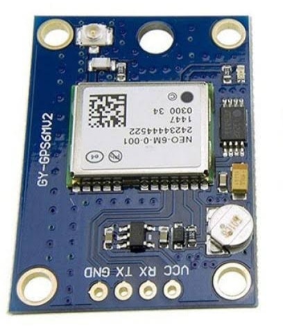
GY-GPS6MV2
- VCC: This pin is used to give a positive power supply in the range of 3.3V-6.0V
- GND: This pin is used for common ground connection.
- TX: This pin is used to transmit the data serially to know the information like time, location, etc.
- RX: This pin is used to receive the data serially, which is used for the configuration of the module.
Firstly check the GY-GPS6MV2 GPS receiver module output microcontroller by connecting it to the PC through the USB to DB9 connector or serial connector before interfacing with any microcontroller. Place the GPS module’s antenna properly.
The circuit diagram of interfacing the GY-GPS6MV2 GPS receiver module to ATmega16 is shown in the figure below. The components required are
– GY-GPS6MV2 module
– ATmega16 microcontroller
– 20×4 LCD
– Power supply
– 10 Kilo Ohms resistor
– Connecting wires.
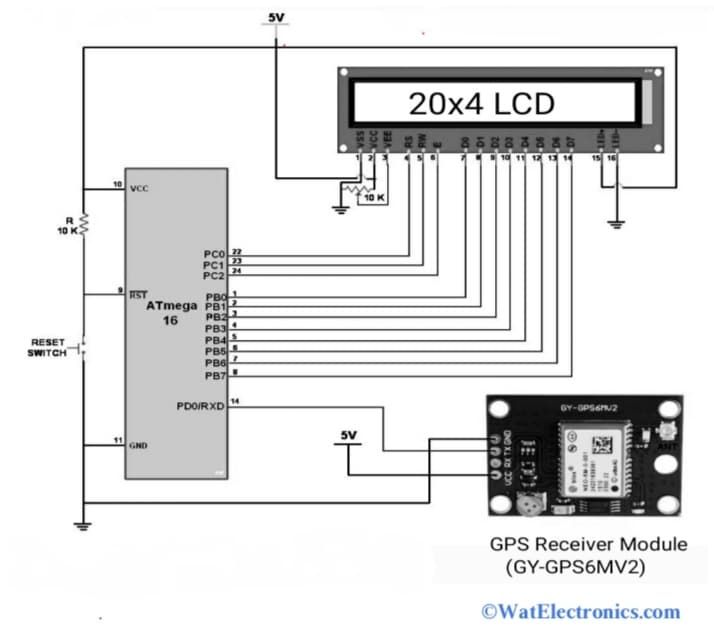
Interfacing GY-GPS6MV2 Module to ATMEGA16
Connections are made as per the above circuit diagram. Connect the VCC and GND pins GPS module to the respective ATmega16. Connect the TX pin of the module to the pin 14 PD0/RXD of Atmega16. Connect the D0-D7 pins (pin 7-14) of LCD to PB0-PB7 pins (pin 1-8) to Atmega16.
The RS, RW, and E (Pin 4, 5, 6) of LCD are connected to PC0, PC1, and PC2 pins (pin 22, 23, 24) of Atmega16. The VCC and VEE pins of the LCD are connected to one end of the 10 Kilo Ohms resistor. While the VSS pin and the other end of the 10K resistor are grounded. The RX pin of the module is not connected.
Upload the interfacing code required to observe the output on the LCD, which is given below.
/*
GPS Information extraction using ATmega16/
#define F_CPU 8000000UL
#define SREG _SFR_IO8(0x3f)
#include <avr/io.h>
#include <string.h>
#include <stdio.h>
#include <stdlib.h>
#include <stdbool.h>
#include <util/delay.h>
#include <avr/interrupt.h>
#include “LCD_20x4_H_file.h”
#include “USART_Interrupt.h”
void convert_time_to_UTC();
void convert_to_degrees(char *);
#define Buffer_Size 150
#define degrees_buffer_size 20
char Latitude_Buffer[15],Longitude_Buffer[15],Time_Buffer[15],Altitude_Buffer[8];
char degrees_buffer[degrees_buffer_size]; /* save latitude or longitude in degree */
char GGA_Buffer[Buffer_Size]; /* save GGA string */
uint8_t GGA_Pointers[20]; /* to store instances of ‘,’ */
char GGA_CODE[3];
volatile uint16_t GGA_Index, CommaCounter;
bool IsItGGAString = false,
flag1 = false,
flag2 = false;
void get_gpstime(){
cli();
uint8_t time_index=0;
/* parse Time in GGA string stored in buffer */
for(uint8_t index = 0;GGA_Buffer[index]!=’,’; index++){
Time_Buffer[time_index] = GGA_Buffer[index];
time_index++;
}
convert_time_to_UTC();
sei();
}
void get_latitude(uint16_t lat_pointer){
cli();
uint8_t lat_index;
uint8_t index = lat_pointer+1;
lat_index=0;
/* phrase Latitude in GGA string stored in buffer */
for(;GGA_Buffer[index]!=’,’;index++){
Latitude_Buffer[lat_index]= GGA_Buffer[index];
lat_index++;
}
Latitude_Buffer[lat_index++] = GGA_Buffer[index++];
Latitude_Buffer[lat_index] = GGA_Buffer[index]; /* get direction */
convert_to_degrees(Latitude_Buffer);
sei();
}
void get_longitude(uint16_t long_pointer){
cli();
uint8_t long_index;
uint8_t index = long_pointer+1;
long_index=0;
/* phrase Longitude in GGA string stored in buffer */
for( ; GGA_Buffer[index]!=’,’; index++){
Longitude_Buffer[long_index]= GGA_Buffer[index];
long_index++;
}
Longitude_Buffer[long_index++] = GGA_Buffer[index++];
Longitude_Buffer[long_index] = GGA_Buffer[index]; /* get direction */
convert_to_degrees(Longitude_Buffer);
sei();
}
void get_altitude(uint16_t alt_pointer){
cli();
uint8_t alt_index;
uint8_t index = alt_pointer+1;
alt_index=0;
/* phrase Altitude in GGA string stored in buffer */
for( ; GGA_Buffer[index]!=’,’; index++){
Altitude_Buffer[alt_index]= GGA_Buffer[index];
alt_index++;
}
Altitude_Buffer[alt_index] = GGA_Buffer[index+1];
sei();
}
void convert_time_to_UTC()
{
unsigned int hour, min, sec;
uint32_t Time_value;
Time_value = atol(Time_Buffer); /* convert string to integer */
hour = (Time_value / 10000); /* extract hour from integer */
min = (Time_value % 10000) / 100; /* extract minute from integer */
sec = (Time_value % 10000) % 100; /* extract second from integer*/
sprintf(Time_Buffer, “%d:%d:%d”, hour,min,sec);
}
void convert_to_degrees(char *raw){
double value;
float decimal_value,temp;
int32_t degrees;
float position;
value = atof(raw); /* convert string into float for conversion */
/* convert raw latitude/longitude into degree format */
decimal_value = (value/100);
degrees = (int)(decimal_value);
temp = (decimal_value – (int)decimal_value)/0.6;
position = (float)degrees + temp;
dtostrf(position, 6, 4, degrees_buffer); /* convert float value into string */
}
int main() {
GGA_Index=0;
memset(GGA_Buffer, 0, Buffer_Size);
memset(degrees_buffer,0,degrees_buffer_size);
LCD_Init(); /* initialize LCD16x2 */
_delay_ms(3000); /* wait for GPS receiver to initialize */
USART_Init(9600); /* initialize USART with 9600 baud rate */
sei();
LCD_Clear();
while (1)
{
_delay_ms(1000);
LCD_String_xy(1,0,”UTC Time: “);
get_gpstime(); /* Extract Time in UTC */
LCD_String(Time_Buffer);
LCD_String(” “);
LCD_String_xy(2,0,”Lat: “);
get_latitude(GGA_Pointers[0]); /* Extract Latitude */
LCD_String(degrees_buffer); /* display latitude in degree */
memset(degrees_buffer,0,degrees_buffer_size);
LCD_String_xy(3,0,”Long: “);
get_longitude(GGA_Pointers[2]); /* Extract Longitude */
LCD_String(degrees_buffer); /* display longitude in degree */
memset(degrees_buffer,0,degrees_buffer_size);
LCD_String_xy(4,0,”Alt: “);
get_altitude(GGA_Pointers[7]); /* Extract Altitude in meters*/
LCD_String(Altitude_Buffer);
}
}
ISR (USART_RXC_vect)
{
uint8_t oldsrg = SREG;
cli();
char received_char = UDR;
if(received_char ==’$’){ /* check for ‘$’ */
GGA_Index = 0;
CommaCounter = 0;
IsItGGAString = false;
}
else if(IsItGGAString == true){ /* if true save GGA info. into buffer */
if(received_char == ‘,’ ) GGA_Pointers[CommaCounter++] = GGA_Index; /* store instances of ‘,’ in buffer */
GGA_Buffer[GGA_Index++] = received_char;
}
else if(GGA_CODE[0] == ‘G’ && GGA_CODE[1] == ‘G’ && GGA_CODE[2] == ‘A’){ /* check for GGA string */
IsItGGAString = true;
GGA_CODE[0] = 0; GGA_CODE[1] = 0; GGA_CODE[2] = 0;
}
else{
GGA_CODE[0] = GGA_CODE[1]; GGA_CODE[1] = GGA_CODE[2]; GGA_CODE[2] = received_char;
}
SREG = oldsrg;
}
When the GY-GPS6MV2 module is interfaced with the Atmega16 microcontroller, the output is generated on the LCD, which displays the time, longitude, and latitude in decimal format. The AVR Atmega16 reads the data serially from the TX pin of the module through the USART communication port with a baud rate of 9600. To extract the information like time, longitude, and latitude analyze the received GPGGA string format.
The transmitted signals from the satellites contain information in the sequence of characters or encoded information (timestamps). To calculate the distance between the satellite and the GPS receiver module, the time (time difference between the time at which the satellite transmits the signal and the time at which the GPS receives the signal) and speed of the signal is measured.
For example, T1 is the transmit time of the signal from the satellite
T2 is the receive time of the signal to the GPS receiver module GY-GPS6MV2.
Time difference = T2-T1
The time difference between GPS signals is shown in the figure below.
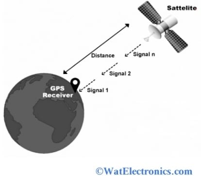
GPS Distance Calculation
Therefore, the total distance from the satellite to the GPS receiver module to track the position and location is calculated from the below formula.
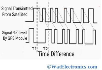
GPS Timing Signals Diagram
Distance = Speed x time
Distance = speed of RF signal X time difference
Position Sensor Applications
The following are the position sensor applications.
- Measurement and automation applications.
- Machinery.
- In vehicle testing.
- Medical equipment.
- Handling and lift systems.
- Research, testing, and lab applications.
- Robotics.
- Aerospace applications.
- Gaming.
- Home appliances.
- Television sets.
- Computers and Gaming.
- Packaging systems.
- Industrial processing.
- Mobile vehicles.
- AutomotiveAutomotive.
- Food and beverage.
Advantages and Disadvantages
The advantages and disadvantages of position sensors depend on their type and application.
> Accuracy is high
> Available at an affordable price
> Resolution is high
> Low sensitive to liquids and harsh environmental conditions
> Maintenance is easy
> More reliable
Disadvantages:
Sometimes sensitive to high temperatures, dust, and other extreme conditions.
> The output signal generated by the position sensor can be interrupted by the electrical and magnetic materials.
> High wear and tear.
Please refer to this link to know more about Parabolic Reflector AntennaMCQs.
Thus, this is all about working, types, and interfacing of position sensors. While selecting a position sensor for a project or application, check the parameters like accuracy, response, resolution, cost, linear Or rotary type, non-contact Or contact type, range of measurement, tolerance, output, and finally the cost.