Any Industrial Process or automated system should run under a controlled process. One such control system which keeps any automated system or a process to be intact is a PID controller. It was initially developed by Elmer Sperry in the year 1911, but it was not evaluated until 1942 when Nicholas and Ziegler added a few parameters and gave life to the PID controller. PID controllers were initially used in Pneumatic control systems and later from the mid-1950s it is extensively used for industrial purposes and adapted to use in many other domains like robotics as well etc. Today, this article helps us in understanding PID controller basics, working, its circuit, types, and a few applications.
What is PID Controller?
PID is termed Proportional Integral Derivative. It is the device that is widely employed in industrial regulatory applications for controlling process variables such as pressure, temperature, speed, flow, and others. This device works with a control loop feedback approach for the regulation of process variables and provides results with more preciseness.
PID instrument measures the error by knowing the difference between desired and actual values and then evaluates the deciding parameters correspondingly. The calculation of error continues till the end of the process.
Using the proportional, one can know the error and this error helps in providing the corrective response value. The proportional term is even termed as proportional gain constant. With integral, the past error values are known and integrated. When the error values are excluded from the system, then the integral value gets increased. And using the derivative, the forthcoming error values are expected depending on the current values.
The regulation impact can be enhanced when the system comes across a sudden rate of change which is again dependent on the derivative. With all the proportional, integral, and derivative operations, the device was named Proportional Integral Derivative (PID Controller).
When these parameters in the PID controller device are chosen inaccurately, then the device shows inaccurate output and also has unsecured results. Here, instability in the device corresponds to the output of substantial excessive gain, particularly when the system shows increased latency (when the system lags), then the gain exceeds the instability factor.
The instability in the device is observed through the Laplace domain using the below formula which is
Hs = Ks*G(s) + Ks * G(s)
Ks corresponds to the system’s transfer function
Gs represents the plant transfer function
Using the product of K(s)*G(s), the system’s stability can be known.
When Ks * Gs = < 1, then the system is considered to be stable.
When Ks * Gs = -1, then the system is considered to be unstable.
The mathematical expression for PID controller is as follows:
ut = Kp et + Ki + Kd de(t)/dt
where Kp corresponds to the coefficient for the Proportional term
Ki corresponds to the coefficient for the Integral term
Kd corresponds to the coefficient for the Derivative term
In the general form of the above mathematical expression, the coefficients of Ki and Kd are substituted as Kp/Ti and KpTd. Here using the terms Ti and Td show some clear physical meaning as these signify integration and derivative of time correspondingly.
The term KpTd represents the time constant which helps the controller in reaching the set point. And Kp/Ti decides the time taken by the controller to tolerate the error constantly either below or above the setpoint. So, the expression can be expressed as:
ut = Kp et + 1/Ti + Td de(t)/dt
PID Controller Block Diagram
Here is the picture that shows the block diagram of the PID controller.
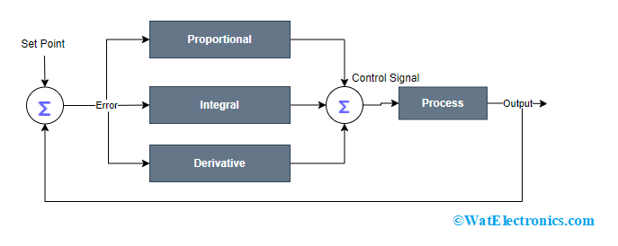
Block Diagram
The input is provided to the proportional, integral, and derivate sections at the same time instant and their corresponding outputs are added using an adder. The summed-up input is provided to the Process that defines the corresponding parameters which are then applied again to the system. So, the Process variable input and the actual input are compared to generate an error, and correspondingly the system’s output is adjusted. This procedure persists till the time error signal reaches zero or else when the process variable value equals to set point.
Mostly many of the controllers consist of three components which are P, I, and D whereas some processes can operate only with two components which can be PI, PD, P, or I. Of the three, one component can be made non-existent by making that term zero.
Working Principle
In the manual operation of the PID controller, the analysis of process variables and adjustment of the control variables is done by the operator occasionally. This adjustment leads to managing the control variables to specified limits like motor inputs, heating components, flow valves, and others. Whereas in the automatic operation of PID devices, the analysis and adjustments are done in an automatic manner continuously.
Mostly, automatic kind of PID controllers are termed as closed-loop systems thus producing either one or more controlling actions which consist of:
- Proportional
- Integral
- Derivative
Proportional
This is also termed a P controller which delivers the output that is proportional to the present error. The error is considered as the variation that exists between the process variable and the setpoint. So, the output is obtained by multiplying the error value with the proportional gain.
Let us consider an example, when the magnitude of error is 40 and proportional gain is 5, then the output is 200. Whereas when the error is ‘0’, then the controller response is also ‘0’. The transient response speed is enhanced by augmenting the proportional gain value. On the other hand, when the proportional gain exceeds the normal value, then the process variable starts to get oscillate at a higher speed which leads system’s stability.
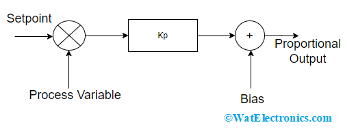
Proportional Controller
Even though the system provides stability when there is good responsive speed, there exists an error. So, there will be no zero error state in the system and the response is shown as follows.
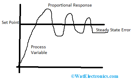
Proportional Response
Integral
This helps is decreasing the system’s steady-state error. The integral factor integrates the error term till the error reaches to ‘0’ value. With this, even a minimal error value results in generating a high integral response. When the error value is negative, then the output of the integral gets decreased. The response speed becomes slow when it is used on its own whereas the steady-state response will be increased. And with the decrement of integral gain, the response speed will increase.

Integral Controller
Derivative
This controller observes how the speed of the process variable modifies and then generates the output in correspondence to the rate of change. The output for the derivative controller is obtained by multiplying the error’s rate of change with the derivative constant.
The derivative controller action enhances the response speed as it provides a quick start to the output which helps in knowing the error’s forthcoming performance. When there is a large derivative term (a large derivative term can be obtained by increased derivative constant), then D-controller responds quickly to the process variable.
In many of the proportional integral derivative controller systems, the derivative term contingents on process variable other than depending on the error. This helps in the elimination of spikes in the output response at the time is sudden changes in the system. So, control systems mainly employ a minimal rate of derivative time as it is highly sensible towards the noise.

Derivative Controller
So, when the optimal gains of proportional, integral, and derivative terms are located properly, then a proper PID controller can be formed.
PID Controller Circuit Diagram
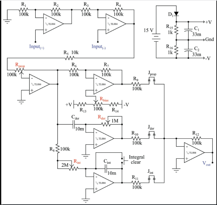
The circuit diagram of the proportional integral derivative controller can be designed by using two quad operational amplifiers along with the input and output voltage signals showing the process variable and setpoint with the corresponding output.
Using only eight operational amplifiers and some electronic components, the PID controller holds the ability to control various industrial applications. The only substantial complication in the construction of the PID system is to achieve slow time constants for differentiator and integration operations through non-polarized capacitors.
PID controller works on ideal PID algorithm where the proportional value allotting to derivative and integral terms. From the above circuit diagram, it can be observed that the inputs for integral and derivative terms get input from the proportional amplifier output.
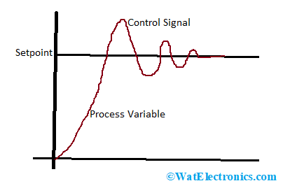
PID Controller Response
Tuning Approaches
In order to get the required output, the PID controller has to be properly tuned. So, the ideal response from the system can be obtained by controller tuning which means the optimal gains of proportional, integral, and derivative terms are tuned properly.
Also, the device is tuned for the avoidance of disturbance where it defines that when the setpoint is altered, then the controller’s output also gets tuned to the altered setpoint. When the PID controller is tuned appropriately, then the output of the system will be automatically tuned to an altered setpoint showing minimal oscillations and damping as well.
To make a PID controller operate with proper tuning, then there exist various tuning methodologies that deliver a required response. A few of those methods are explained below.
Trial & Error – It is also termed a manual tuning approach and it is an uncomplicated technique. Here, initially, the proportional value is increased until the controller gets to the reach of oscillating response but at this time the system should not be away from stability and keeping values of integral and derivative terms as zero.
Later, the value of the integral term is maintained in such a way that the oscillation system ends. Afterward, the derivative value is maintained to deliver a quick response.
Zeigler Nichols – Here, initially the values of integral and derivative terms are to be set to ‘0’. The proportional term value is increased till the point of ultimate gain (gain where the output loop starts to oscillate). Using the ultimate gain and oscillation period, the PID controller’s gain can be known which is like below:
| Controller Type | Proportional
(value in ultimate gain) |
Integral
(value in ultimate gain) |
Derivative
(value in ultimate gain) |
| P | 0.5 | ||
| PI | 0.45 | 0.54 (Ku/Tu) | |
| PD | 0.60 | 1.2 (Ku/Tu) | 3 [(KuTu)/40] |
Ku =ultimate gain and Tu = Oscillation period
Process Reaction Curve – It is termed as Cohen Coon tuning methodology. Here, a process reaction curve is generated initially with respect to disturbance. With the process reaction curve, controller gain, derivative and integral times are known. One can observe this curve when the system operates in an open-loop step test. In this curve, the values of slop, dead, and rise time of the curve can be known and those are the proportional, integral, and derivative values.
Software – There are various software packages to perform loop optimization and controller tuning. These software packages collect information and prepare the corresponding mathematical models.
Relay – It is also called as Astrom Hugglund technique of tuning PID controller. In this method, the output switches between two control variable values, and these values are selected where those should exceed the setpoint values.
- When the process variable value does not exceed the setpoint, then the control output is maintained at a higher value.
- When the process variable value exceeds the setpoint, then the control output is maintained at a lower value and this forms the output waveform.
The output waveform’s amplitude and period are calculated and these parameters are helpful in knowing the oscillation period and ultimate gain.
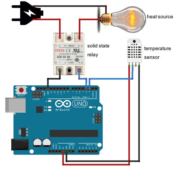
PID Implementation Using Arduino
As discussed above, the mathematical equation for a controller is given as
ut = Kp et + Ki + Kd de(t)/dt
This equation is written in the continuous/analog domain. Whereas many of the controllers implemented these days are in digital form or using microcontrollers such as Arduino. So, the analog equation has to be converted into digital/discrete format and it is as below.
u[n] = Kp e[n] + Ki + Kd [e(n) – e(n-1)]/T
As per the above equation, each signal should be treated as discrete samples as Arduino measures feedback signals in discrete form. In the digital form,
- Kp is obtained by multiplying the gain with the digital error signal
- Ki is the sigma addition
- Kd is a variation between the previous and current errors.
In the digital format, the control signal (N) is calculated discretely at every time instant ‘t’, and ‘T’ is considered as sampling time or constant time interval. The code implementation of the PID controller in Arduino is written as below:
double sensed_output, CS;
double setpoint;
double Kp; //coefficient of the proportional term
double Ki; // coefficient of the integral term
double Kd; // coefficient of the derivative term
int T; //sample time in milliseconds (ms)
unsigned long last_time;
double Te, Le; // Te = Total error and Le = Last error
int maximum_control;
int minimum_control;
void setup(){
}
void loop()
PID_Control(); // This function calls the PID controller at each ‘T’ and delivers a control signal
}
void PID_Control()
{
unsigned long current_time = millis(); //From the time the Arduino starts the program, the current time returns the number of milliseconds
int delta_time = current_time – last_time; //variation between current and last time intervals
if (delta_time >= T)
{
double error = setpoint – sensed_output;
Te += error; //stores the error – integral term
if (Te >= maximum_control)
Te = maximum_control;
else if (Te <= min_control)
Te = minimum_control;
double delta_error = error – Le; //It shows the error variation for derivative term
CS = Kp*error + (Ki*T)*Te + (Kd/T)*delta_error; // computation of PID control
if (CS >= maximum_control)
CS = maximum_control;
else if (CS <= minimum_control)
CS = minimum_control;
Le = error;
last_time = current_time;
}
}
In the above code in order to get the sampling time at similar intervals, the current time is stored through an inbuilt function in Arduino called millies. This millies function returns the number of milliseconds from the time the Arduino starts the program. The delta time is obtained by calculating the variation between current and previous time intervals so that it gives the update control signal at each t second.
And the error is known by calculating the difference between the setpoint and sensed output. Whereas total error is obtained by integrating the error. At each ‘t’ instant, the delta error corresponds to the derivative term. So a control signal is formed by summing up all the above values. When the next loop occurs, the current error is treated as a previous error and this process continues.
Please refer to this link to know more about PID Controller MCQs
Applications
The main application of PID controller is in adjusting a few of the physical parameters in control systems such as pressure, flow value, temperature, and others. This device is also helpful in maintaining these physical parameters at a constant value. Apart from these, a few of the other PID controller applications are:
- In many industrial applications, there will be huge furnaces for heating and melting multiple components. Here, the temperature values are to be monitored continuously so that the furnace temperature is maintained at the required constant value. In order to achieve this, a PID controller is required.
- It is employed as a high-level power point tracking controller device.
- Used in power conversion devices.
- In order to maintain the humidity and temperature levels in various areas, these PID controllers are used in different domains such as pharmaceutical, research, chemical, and engineering.
PID Controller Advantages and Disadvantages
There are many advantages of a proportional integral derivative controller device and those are
- These are process-dependent devices.
- Provides high responsiveness.
- Shows no complexity in tuning and functionality of the device.
- PID devices are economically available.
- One can obtain precise values of the setpoint so that accurate pressure and temperature values can be maintained.
A few of the limitations of PID are:
- These devices are easily vulnerable to noise.
- Regular tuning of the device reduces its life span and functional ability.
- Easily shows instability when it is not tuned properly.
- By continuously altering the load, the performance of the system will be reduced.
On the whole, this is a detailed explanation of the PID device. This article helps us to understand PID controller working, circuit, block diagram, applications, and advantages. To know more about PID please click
- What is PID full form?
PID is termed Proportional Integral Derivative.
- Why PID controller is used?
Using a PID device, one can regulate the values of control variables like temperature, flow, speed, pressure, and others.
- What is PID in the PID controller?
P (Proportional) – One can know the error and this error helps in providing the corrective response value.
I (Integral) – With integral, the past error values are known and integrated. When the error values are excluded from the system, then the integral value gets increased.
D (Derivative) – Using the derivative, the forthcoming error values are expected depending on the current values.
- What is the difference between PI and PID controllers?
Using a PI controller, huge noises or disturbances can be eliminated at the time of system functionality. Whereas PID controller helps in the management of higher-order capacitive processes.
5. What are some examples of when a PID controller would be used?
A PID controller would be used in any situation where you need precise control over output. For example, in thermostats for maintaining indoor air temperature, or in air conditioners for keeping outdoor air temperature cool.
6. How do I know if my system needs a PID loop?
If your system requires constant adjustment due to changes in input, then you could use a proportional-integral-derivative loop. In these cases, it’s important not to let external factors affect your desired output values (such as changing room temperature). Instead, create a model that adjusts based on only those factors that are actually relevant (such as sunlight hitting the window or someone opening it).
7. How do I get my PID controller to work properly?
Attach the PID controller to a device with a very large motor (such as an ice cream maker, blender, or drill press) and spin it at a very fast speed until you feel that it is roughly in its middle range.
8. Difference between a PLC and PID Controller?
PLC and PID controllers are both industrial control systems, but they have important differences.
PID is a type of control system that works by calculating the difference between a process value (such as the temperature of a furnace) and a setpoint (a temperature that the system should be maintaining). The PID controller then adjusts the input to the process (the heat output of the furnace) in an attempt to minimize that error.
PLCs, or programmable logic controllers, are also used in industrial environments. Instead of calculating an error against a setpoint, though, PLCs accept input from sensors in their environment and use those inputs to determine what actions to take in order to maintain certain conditions at other sensors
