The PIC microcontroller was designed and developed in 1993 by Microchip Technologies. These controllers are mainly used for interfacing computers & every peripheral device. So, it is named a peripheral interface controller. After that Microchip launched many PIC series microcontrollers to use in any application. The programming of PIC microcontrollers can be done using different software which is already available in the market but still, assembly language is used by some people for programming these controllers. Microchip developed some most common & advanced softwares & compilers. PIC microcontroller needs an IDE tool for programming A compiler converts our program into a readable form of MCU like HEX files and IPE is used for dumping hex files into the PIC microcontroller. So this article discusses an overview of one of the types of PIC microcontrollers like PIC12f675 Microcontroller – pin configuration and its applications.
What is PIC12f675 Microcontroller?
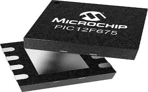
PIC12F675 microcontroller is a small, low cost and mid-range 8-bit controller designed by Microchip Technology. This controller is developed by using high-performance-based RISC architecture. This is a very powerful microcontroller because it functions with 200 nanosecond instruction execution and also it is very easy to program. So it is mainly designed for low-cost systems for learning as well as experimenting. This controller is not used for making complex applications due to a limited set of capabilities but it is frequently used by engineers & beginners due to less cost & availability in small size.

PIC12F675 Microcontroller
Pin Configuration: PIC12F675 Microcontroller
The pin configuration of the PIC12f675 microcontroller is shown below. This controller includes 8 pins where 6 pins are used like I/O pins.

Pin Configuration
- Pin1 (VDD): Positive Power Supply
- Pin2 (GP5/T1CKI/OSC1/CLKIN): General purpose Input/Output pin-5, Timer1 external CLK i/p, oscillator pin-1 and external CLK i/p source.
- Pin3 (GP4/ AN3/ T1G/OSC2/CLKOUT): General purpose Input/Output pin-4, Analog input-3, Timer1 gate and Oscillator pin-2.
- Pin4 (GP3/MCLR/VPP): General purpose Input/Output pin-3, Master Clear Input or Reset pin, and the Programming voltage.
- Pin5 (GP2/AN2 /T0CKI/INT/COUT): General purpose Input/Output pin-2, analog input2, timer0 CLK input, external interrupt and output of comparator.
- Pin6 (GP1/AN1/CIN-/VREF/ICSPCLK): General purpose Input/Output pin 1, analog input-1, the input of the comparator, external voltage reference & serial programming CLK.
- Pin7 (GP0/AN0/CIN+/ICSPDAT): General purpose Input/Output pin, analog input0, comparator input, and serial programming data Input/Output.
- Pin8 (VSS): It is a GND pin.
Features & Specifications:
The features and specifications of the PIC12f675 microcontroller are discussed below.
- It is an 8-pin microcontroller.
- It is available in PDIP Package/ Case.
- Programmable pins – 6.
- Mount is Through Hole.
- It has a mid-range 8-bit CPU.
- Its access time is 20 µs
- Its operating voltage ranges from 2V to 5.5V.
- It has a 4-Channel, 10-bit ADC Module.
- 8-bit/16-bit Timer Module.
- It includes one comparator.
- It has a 4 MHz Internal Oscillator.
- Program memory is 1.75KB.
- The speed of the CPU is 5 MIPS.
- RAM is 64 Bytes.
- Data EEPROM is 128 Bytes.
- Density 14 kb
- Frequency 20 MHz
- Interface RS-232, USB
- Max Operating Temperature 85 °C
- Max Power Dissipation 800 mW
- Its memory size is 1.8 kB.
- The type of memory is FLASH.
- The nominal current supply is 100 µA.
- A/D converter is 1.
- ADC channels-4.
- A number of timers or counters – 2.
- Its Height x Length x Width is 4.953 mm x 10.16 mm x 7.112 mm.
Alternative PIC12F675 microcontrollers are; PIC12F629, PIC16F505, PIC16F676, PIC16F72, PIC16F876A, PIC16F886, PIC16F873A, PIC12F508, PIC16F252 and PIC12F683.
PIC12f675 Microcontroller Architecture
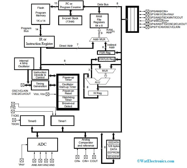
The PIC12f675 microcontroller architecture or functional block diagram is shown below. This microcontroller performs different functions like other PIC microcontrollers which are discussed below.

PIC12f675 Architecture
Timer
This PIC microcontroller includes two timers one is an 8-bit timer and the other one is a 15-bit timer which is used as a timer & a counter. The timer mode is used for creating the delay within any function that increases the instruction cycle whereas the counter mode helps in counting the no. of intervals within any function. This mode is used for incrementing the falling & rising edge of the pin.
Oscillator Start-up Timer & Power Up Timer
The oscillator start-up timer is an extremely helpful feature because it maintains the module within the reset mode until the crystal oscillator turns stable. Likewise, a power-up timer produces 72ms of delay once you turn ON the device, which provides a correct time to the power supply for stabilizing as well as providing power signals in a permanent way.
Brown Out Detect
The brownout detects (BOD) is a very helpful function used to reset the module when the voltage supply falls below a brownout threshold voltage. It is also called brownout reset (BOR). This mode provides various voltage ranges for protecting the module when the power goes down at the voltage supply line. Here, it is very significant to note that, the power-up timer should be permitted to produce the delay in returning the device from a brownout detect function. This function includes four operating modes and these can be programmed by simply setting/clearing BOREN bits.
ICSP or In-Circuit Serial Programming
This PIC microcontroller comes with ICSP which is very helpful in programming the module once its installation is done within any project. Once the module programming is done before setting up, then you have to verify & also test the program each time it’s installed within the project. ICSP provides you the flexibility to verify the compiled program within the project so that you can make the necessary changes very easily & makes it very compatible with the running application.
MCLR or Master Clear Reset
In this module, the MCLR is a pin-4 within this controller which calls the outside reset for the controller. Here, the reset is arranged by maintaining this pin-4 LOW that not depends on the inside resets. In the MCLR executing procedure, the noise filters available for executing procedure & are extremely helpful to eliminate and notice minute pulses.
Watchdog Timer
This microcontroller has an inbuilt watchdog timer that takes the microcontroller to a reset location if the program hangs up throughout compilation or gets jammed in the infinite loop. This is also known as a countdown timer.
Memory
The memory in the PIC controller helps in storing the no. of instructions within the code form. Here this memory is separated into two types program memory and data memory which are discussed below.
Program Memory
The program memory (ROM) in this microcontroller stores the data permanently & includes approximately 1.7K of memory space. So this type of memory doesn’t depend on the source of power supply & comes with the capability to keep the data in the lack of a power supply. This memory mainly includes a 13-bit program counter for addressing 8k x 14 program space wherever the interrupt vector at 0004h lies as the reset vector waits at 000h & is loaded through the microcontroller.
Data Memory
The data memory (RAM) is used for storing the data momentarily. This memory mainly depends on the power supply & cannot store data in the lack of the power supply. This memory is classified into two banks and these two banks further include two types of registers SFR or Special Function Registers and GPR or General Purpose Registers. Each bank’s first 32 locations are simply assigned to SFRs that can manage the peripheral functions which are categorized as core & peripheral.
Compiler
PIC controller has a standard compiler created by Microchip namely MPLAB C18 Compiler. In the compiler, the code which we write will generate a hex file after that it is uploaded into the microcontroller for executing the various instructions.
A compiler & Burner are two dissimilar things. The burner is mainly used for burning the necessary program within the microcontroller whereas the compiler is mainly used for writing the program for the microcontroller. So the standard burner utilized for the PIC microcontroller is PICKit3.
Safety Alarm Button with PIC12f675 Microcontroller
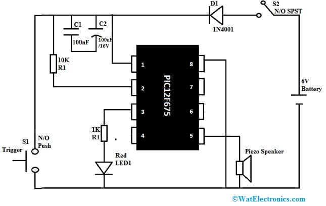
The circuit diagram of the safety alarm button using the PIC12f675 microcontroller is shown below. This circuit is an audio alert unit that gives an alert tone whenever someone pushes the trigger button. This circuit can be powered with four 1.5V AA cells or a 6V battery by connecting them in series.
The required components to design this safety alarm button mainly include switches – S1 & S2, resistors – 1K & 10K, pic12f675 microcontroller, piezo speaker (PZ1), capacitors C1- 100nF,100uF/16V,1N4001 diode, and 6V battery. Connect the circuit as per the connections shown in the circuit below.

Safety Alarm Button with PIC12f675 Microcontroller
Working
This circuit is powered by switching ON the S2 power switch. Once the circuit is activated then the LED1 will blink three times for indicating that the system has been activated. After that, the PIC12F675 microcontroller will remain for a few seconds before it begins monitoring the condition of the trigger switch.
After some delay, when the microcontroller notices S1 is closed then it will drive the PZ1 piezo speaker and this speaker will stay on only if the switch ‘S1’ is enabled. If the S1 trigger switch is disabled then the PZ1 speaker will not sleep instantly, although it will remain ON for a few seconds with a somewhat different frequency.
Code
The following program is written in C & compiled through MikroC Pro for the microcontroller.
#include<pic12f675x.h>
sbit Sensor_IP at GP5_bit;
sbit LED at GP4_bit; // LED O/P
unsigned short trigger, counter;
void Get_Delay()
{
Delay_ms(300);
}
void main()
{
CMCON0 = 7;
TRISIO = 0b00101000;
GPIO = 0;
Sound_Init(&GPIO,2);
LED = 1;
Get_Delay();
LED = 0;
Get_Delay();
LED = 1;
Get_Delay();
LED = 0;
Get_Delay();
LED = 1;
Get_Delay();
LED = 0;
Delay_ms(10000);
counter = 0;
trigger = 0;
do {
while (!Sensor_IP) {
Sound_Play(3500, 600);
Delay_ms(500);
trigger = 1;
counter = 0;
}
if (trigger) {
Sound_Play(2900, 600);
Delay_ms(500);
counter = counter+1;
if(counter == 10) trigger=0;
}
}while(1);
} // End main()
Applications
The applications of the PIC12f675 microcontroller include the following.
- This PIC microcontroller is simply used for industrial, automotive, appliances entry-level & consumer product applications that need field re-programmability.
- This microcontroller is mainly developed for low-cost system applications.
- This is perfect for remote monitoring points & small sensor-based applications.
- This controller is mainly used for experimenting & learning for beginners and engineers because this controller includes a flash memory rewrite cycle.
- This controller is sufficient to develop fundamental programs for beginners because it has 2KBytes of flash memory.
- These are used in low-end applications like temperature monitors, scrolling displays, etc.
- It is used as a development board for learners, used in hobbyist projects, display units & beginner applications.
- Microcontrollers are a practical, affordable, and flexible solution to many challenges of circuit design and modern control systems.
Please refer to this link for 24LC1026 Serial EEPROM.
Please refer to this link for PIC12f675 MicrocontrollerDatasheet,
Thus, this is an overview of the PIC12f675 microcontroller – pin configuration, specifications, functions, circuit, and applications. By using these microcontrollers, some real-time embedded as well as control system applications can be easily performed because these microcontrollers are available with high efficiency to perform many instructions. These types of microcontrollers are not expensive and perform many operations on a single IC. Here is a question for you, what are the other PIC microcontrollers?