In order to have interference with the outside world using microcontrollers, it can be done through pins. These pins act as physical points for an integrated circuit where a PCB connection can be established. Each pin has its own circuitry, and it is configured to pins to allow interference with various kinds of circuits. And the most important point is to select the appropriate pin configuration in the design of an embedded system. Today, this article explains open-drain output configuration, how it is configured, its applications, and its advantages.
What is an Open Drain?
It is also called Open Collector which is a transistor having a connection with the ground pin. In a simple way, it behaves like a switch that gets connected or disconnected depending on the input signal. This open-drain configuration permits different devices to establish communication bi-directionally on one wire. This is generally considered as a mode where it provides only pull-down functionality. This is the basic open-drain definition.
Circuit and Working
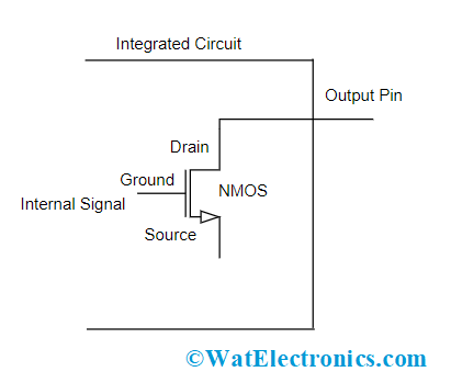
In most of the integrated circuits, the observed output configuration type is open-drain. As a replacement for outputting a signal with a corresponding current or voltage, the output is fed to the base terminal of the NPN transistor, and the collector terminal is externally connected to the integrated circuit pin. The emitter terminal has an internal connection with the grounded pin. When the output circuit is in MOSFET configuration, then it is termed as open drain circuit and it operates in the same way.

Open Drain Circuit
In the working of open collector devices, they allow current flow either in the logic ‘0’ low voltage active state or logic ‘1’ high voltage non-active (high impedance) state. The open-collector devices generally function using an external pull-up resistor which allows the signal line to be in high phase up, so that to the device connected on the wire flows enough amount of current in order to pull the line to low and to the signal the start of a communication.
When all the devices which are connected to the signal wire are in a non-active state, then the pull-up makes the wire at a high voltage phase. When one or more devices function in the active state, then the voltage of the signal wire moves to low.
In the open drain working, the signal wire also functions in bi-directional which corresponds that the device can have both input/output signals on the wire at the same period of time. Along with the regulation of the pins state, which is connected to the signal wire, it can also recognize the level of voltage of the wire.
Even though the output of the open collector device is in the high state, the signal wire which is attached to it might be in low state because of the other device that is connected to the signal wire. So, with the bi-directional behavior, the open collector device can be useful for the interconnection of multiple devices on a single line.
Open Drain Configuration
The open-drain configuration is employed at the controller’s output port in order to lessen the output circuitry. When the output port is fixed at open-collector/drain state, then there is no additional equipment necessary for pulling down the pin’s output value.
In this configuration, it turns off entire pull-up transistors and only drives pull-down transistors of the port pin when the latch pin of the port is in logic ‘0’ state. In order to function in logic output, then the port is configured in a manner such that it has a resistor-connected VDD terminal and an external pull-up transistor. In this state, the pull-down approach is similar to a quasi-bidirectional method.
In order to employ analog input pin as high-impedance input and a comparator is enabled state, then that pin has to be in the configuration of open collector and the related register bit has to be in ‘1’ state.
In both of the scenarios, the point to be noted is that the open drain/collector is a part of the output transistor which is directly connected out to a pin that is on the external side of the integrated circuit.
The below picture represents the open drain configuration.
Types of Output Configurations in Comparison with Push-Pull and Pull Up Mode
In digital sensing applications, the crucial part is to select the suitable output configuration where the main options are open collector, push-pull and push-up. To know these configurations, let us know a few terms which are explained below:
Floating Pin – A pin is considered to be in a floating state when it is not connected to any other pins and also it is not led by any circuit in the IC. The voltage level of the floating pin is unclear and cannot be predicted. Also, when a high impedance pin is not led either by pull-up or pull-down circuits, then it is also called a floating pin.
High Impedance – A pin that has a high impedance essentially takes out its impact on the electrical circuit to which it is connected. It is usually not driven actively and is in a floating state except it is connected to any other external device.
Open Drain v/s Push Pull
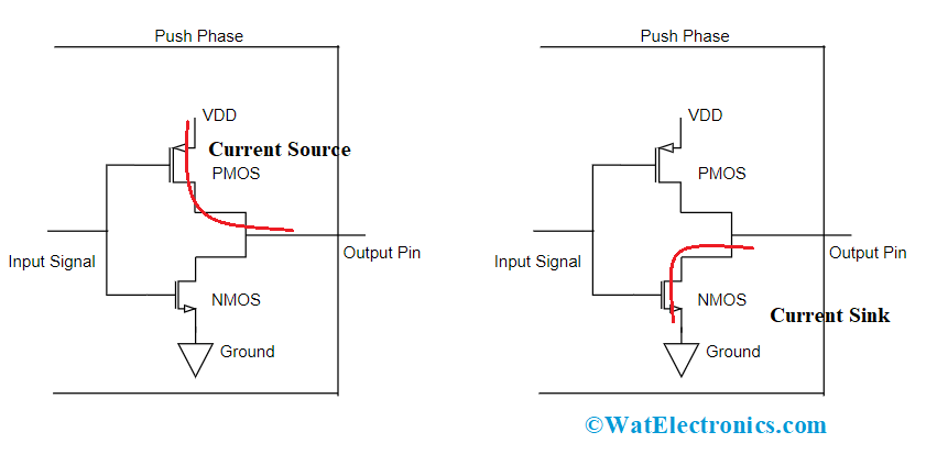
Push-pull output configuration is the most implemented type where the name itself indicates that this configuration holds the ability to drive two different output levels. One is to sink current from the load section and the other is to source current to the load section. This configuration is implemented through switches. The two scenarios push and pull representations are shown below:

Push Pull Output
The open drain advantages and disadvantages in comparison with push-pull configuration are:
| Open-Drain Configuration | Push-Pull Configuration | |
| Benefits |
|
|
| Drawbacks |
|
|
| Output | When the output is at high, then the pin will be connected to the power supply using NPN switch, and when the output low state, the pin gets connected to the ground using PNP switch | When the output is at high, then the pin will be connected to the ground using a switch, and when the output low state, the pin will be in a floating state as the switch is turned OFF |
On the whole, push-pull configuration is selected when there is the requirement of minimal circuitry, and an open collector configuration is chosen for the requirements of interfacing with various system voltages, load switching, and when multiple device outputs are to be connected to a single bus.
Open Drain v/s Pull Up
In order to know the pull-up concept, let us understand output possibilities in an open-collector configuration.
- In the open-drain configuration, the logic at the pin defines that it drives the device only to the logic ‘0’ state, and the other possible condition is a high impedance state where it requires the implementation of a transistor.
- When the drain terminal moves to open state (corresponds that the device is in ‘OFF’ condition), then the pin floats at a high impedance state.
- Making the pin to high logic (logic ‘1’) from logic ‘0’ needs additional components and for this external pull-up resistors are used. Upon the activation of the pull-up resistor, the input pin changes its state to Vdd.
Output mode in open-drain configuration simply does not have a PMOS transistor. When the switch is in the OFF state, the drain gets opened and output moves into a floating state. In this configuration, the pin is only pulled up but not pulled down. The open-drain configuration is of no use when it does not support pull-up functionality.
In order to make this configuration applicable in real-world scenarios, either an external or internal pull-up resistor has to be used. These days, all the microcontrollers are provided with a pull-up resistor for the output pin.
Applications
The applications of open drain include the following.
- The crucial application is in summing, weighting, and limiting both analog and digital logic.
- Used in vacuum fluorescent displays and in Nixie tubes
- Used in SCS-1 devices for the purpose of electrical signaling.
What is open-drain used for?
Open collector/drain presents high impedance either high or low voltage is applied to the gate terminal.
What is open drain and wired or?
The open-drain technique is used to establish communication between multiple devices bi-directionally on a single wire.
Is open-drain high impedance?
When the device does not use a bus, then the output of the open collector is in high impedance.
What is an open-drain transistor?
Open drain transistor represents that the output pin is led by only one transistor where it pulls the pin to only one voltage level usually to the ground.
Does open-drain need pull up?
Open-drain configuration requires a pull-up resistor so that the output will be properly at high.
What is an open-drain buffer?
The open collector/drain buffer is 74LVC1G07 IC with open-drain output. This buffer when connected with other open-collector outputs is suitable for the application of active low (wired-OR) or wired-AND functions.
Please refer to this link to know more about Analog Electronics MCQs.
So, this is all about the concept of the open drive. This article has clearly focused on explaining what is open-drain configuration, its comparison with push-pull and pull-up configurations, circuits, and applications. Also, know how an open-drain output configuration is used in driving LEDs?