The non-inverting amplifier is the basic circuit obtained from amplifiers. As it name goes the circuit helps in achieving the non-inverted output at the final stage. Although the inverting amplifier is preferred in many cases it has two drawbacks. Firstly, the output obtained at the final stage of it is an inverted one. Obtaining an inverted output further requires any other setup to be connected to further invert the inverted output. The second drawback which is the most major one is that the impedance at the input is dependent on the resistor connected at the input.
To prevent the effect of loading in the larger systems the impedance considered must be of greater value that is up to 10 times in comparison with the preceding circuit. For this reason, the value of the resistor connected at the input must be chosen accordingly. This further creates other problems in the circuit. It can be overcome by the non-inverting amplifiers.
What is a Non-Inverting Amplifier?
The amplifier in which the input signal is applied to the non –inverting terminal so that the output obtained is non-inverted. It is similar to that of the inverting amplifier. The same parts of the inverting amplifier are utilized in this amplifier. The only design criteria that must be chosen is that the non-inverting amplifier must possess the high value of the impedance at the input.
Circuit Diagram
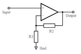
The non-inverting amplifier are designed using an the operational amplifier. In the op-amps there are three basic terminals among those three two will be the input terminals and one is for output consideration. The applied input to the respective terminal decides whether it is an inverting one or non-inverting one. If it is inverting the input is applied to the negative terminal otherwise if the input is applied to the non-inverting/positive terminal.
The circuit designed for a non-inverting amplifier consists of a basic op-amp where the input is connected to a non-inverting terminal. The output obtained from this circuit is a non-inverted one. This is again feedback towards input but to the inverting terminal via a resistor. Further, one more resistor is connected to the inverting terminal in concern to connect it to the ground. Hence the overall gain of the circuit is dependent on these two resistors that are responsible for the feedback connection. Those two resistors will behave as a voltage divider of the feedback fed to the inverting terminal. Generally R2 is chosen to be greater than the R1.

Non-Inverting Operational Amplifier Circuit
Non-Inverting Amplifier Gain
As already discussed the constructional view of the non-inverting amplifier it can be considered that the inputs applied at both the terminals are the same. The voltage levels are the same and even the feedback is dependent on both the resistors R1 and R2. In this way, it makes simple and easy to determine the gain for such types of amplifiers. As the voltage levels applied for both the terminals remain the same indirectly results in the gain levels to be high.
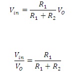
The voltage level determined at the inverting terminal is because of the presence of the potential-divider circuit. Then this results in the equation of the voltage that is:

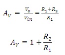
But the gain is the ratio between the ratios of the output values to input values of the applied signals.
Therefore,

Where;
Av represents the overall gain obtained in the circuit.
R1 represents the resistance connected to the ground.
R2 represents the resistor connected to the feedback.
The resistance considered in the above equation is in ohms.
Non-Inverting Summing Amplifier
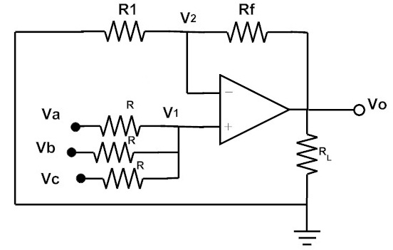
A summing amplifier is can also be constructed using the non-inverting Op-Amp. When an different voltage signals in parallel are fed to the non-inverting terminal of the Op-Amp then it becomes a Non-Inverting Summing Amplifier.

Non-Inverting Summing Amplifier
If the used resistors in the circuit are considered to be equal in terms of resistance. In that case, the equation for the output can be determined as
![]()
Output Wave forms
This amplifier generates the output the same as that of the applied input signal. Both the signals that are applied input and the generated output are in phase. Because of this reason, the potential difference across both the terminals remains the same.

Output Wave form of the Non-Inverting Amplifier
Advantages and Disadvantages of Non-Inverting Amplifier
The advantages of the non-inverting amplifier are as follows:
- The output signal is obtained without phase inversion.
- In comparison to the impedance value of the input at the inverting amplifier is high in the non-inverting amplifier.
- The voltage gain in this amplifier is variable.
- Better matching of impedance can be obtained with the non-inverting amplifiers.
- It has a positive voltage gain.
The disadvantages of the non-inverting amplifier are as follows:
- More stages are utilized based on the requirement of achieving desired gain.
- Based on the respective amplifiers chosen the input and the output resistance gets varied.
The above are some of the advantages and disadvantages of non-inverting amplifiers.
Applications
The applications of the non-inverting amplifiers are as follows:
- The circuits that have the requirement of the high input impedance non-inverting amplifiers are utilized.
- To isolate the respective cascaded circuits these are used.
- In the varying gains consideration, these amplifiers are used.
Please refer to this link to know more about Inverting Amplifier MCQs, Non-inverting Amplifier MCQs
These non-inverting amplifiers have various applications in terms of the higher values of input impedance. These amplifiers possess unit gain value. It has many valid features in terms of negative feedback applied to it. The output has a minimum or zero value of resistance. Because of this reason, the matching of the other circuits becomes easier. The separation of cascaded circuits even becomes simpler. What can be the IC number of this type of Operational amplifier that is widely used in various practical applications?