In designing electrical circuits, the process of analyzing the circuit is a crucial part, which deals with voltage and current at each branch or node of the circuit. The process of analyzing the circuit is nothing but finding out the unknown voltage and current values of a branch or node. However, this process is complex because more components are connected together in the circuit. Hence the proper technique should be followed to determine the current and voltage. There are two possible techniques to analyze the circuit, they are, mesh current analysis or mesh analysis, node voltage analysis, or nodal analysis. From both techniques, it is necessary to select one, based on the circuit complexity and time. If a circuit contains current sources, then the nodal analysis is the best method and very simple. If a circuit consists of voltage sources, then the mesh analysis is best to determine unknown quantities because it takes less time for calculation. This article gives a brief explanation of nodal analysis with voltage and current sources.
What is Nodal Analysis?
If an electrical circuit consists of both voltage and current sources, then it is difficult to choose one of the techniques of mesh and nodal analysis, in such cases, if the number of current sources is larger than the voltage sources, then this analysis is the best technique that should be used. The voltage source should be converted to an equivalent current source. When two or more circuit components or elements are connected together, then it is called a node. Each node in the circuit is analyzed as a node voltage and the process of analyzing the node is called nodal analysis.
The technique that is used to find the branch currents flowing in an electrical circuit is called nodal analysis or node voltage analysis. This analysis is generally used to determine current and voltage in the circuit by assigning nodes that can be applied for parallel circuits, which have a common ground terminal.
This technique uses KCL (Kirchhoff’s current law) to determine the voltage around the circuit. Solving the circuit requires a fewer number of equations when compared to mesh analysis. The nodal analysis based on the concept of matrix analysis.
As we know that, the nodal analysis based on KCL, which means, the sum of all incoming currents of the node is equal to the sun of outgoing currents from the node of a circuit. It is used to determine the potential difference between the connected components in the circuit. To determine the voltage at each node, it is necessary to assign two types of nodes to the circuit, that is reference node and non-reference nodes.
The point that acts as a reference to all other nodes is known as the reference node. While the non-reference node contains fixed voltage, which is termed as node voltage that is to be determined using the nodal analysis. The number of node equations required to solve the circuit is n-1. That means the number of non-reference nodes of the circuit is equal to the obtained node equations
Difference between Mesh and Nodal Analysis
The difference between mesh and nodal analysis is given in the tabular form.
|
Mesh Analysis |
Nodal Analysis |
| This method is used to determine the current circulating a mesh or loop in a closed path of any electrical circuit. | This method is used to determine the unknown voltage drop around the circuit between two or more nodes. |
| It is also known as Mesh Current analysis or mesh loop analysis | It is also known as node voltage method or node voltage analysis or supernode analysis |
| It is based on Kirchhoff’s Voltage Law(KVL) | It is based on Kirchhoff’s current law(KCL) |
| It is applicable for planar circuits. | It is applicable for parallel circuits with a ground terminal. |
Nodal Analysis with Current Source
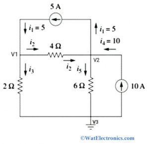
Consider the following circuit to calculate the node voltages using nodal analysis with a current source. This method is very simple and the step-by-step procedure in solving the circuit is given below.

Nodal Analysis with Current Source
From the above circuit, there are 3 nodes. Where V1 and V2 are the non-reference nodes, and V3 is the reference node.
Step 1: Identify and assign the node voltages V1, V2, and V3. Label the directions of branch currents flowing in the circuit with respect to reference node V3.
Step 2: Obtain the node equations by applying KCL to all nodes 1 and 2 except the reference node. And then apply ohm’s law to the obtained KCL equations.
By applying KCL to node 1, we get
I1 = I2 + I3… … … eq 1
By applying KCL to node 2, we get
I2 + I4 = I1 + I5… . . . … eq 2
Step 3: Apply Ohm’s law to the KCL equations of nodes 1 and 2.
By applying Ohm’s law to node 1 KCL equation, we get,
I1 = I2 + I3
5 = [(V1 – V2) /4] + [(V1 – 0) / 2]
Simplify the above equation
3V1 – V2 = 20……..eq 3
By applying Ohm’s law to node 2 KCL equation, we get,
I2 + I4 = I1 + I5
[(V1 – V2) /4 ]+10 = 5 + [(V2 – 0) /4]
After simplifying the above equation, we get,
-3V1 + 5V2 = 60……….eq 4
Step 4: Solve the node equations 3 and 4 obtained by Ohm’s to determine the node voltages V1 and V2
3V1 – V2= 20
-3V1 + 5V2 = 60
By using the elimination method we get,
4V2 = 80
Therefore V2 = 20 Volts
Substitute the value of V2 in eq 3, we get
3V1 – V2 = 20
3V1 – 20 = 20
3V1= 40
V1 = 40/3=13.33 Volts
Therefore the obtained node voltages are, V1= 20 Volts and V2= 13.33 Volts
Nodal Analysis with Voltage Source
There are two possible cases to determine the node voltages using nodal analysis with a voltage source.

Nodal Analysis with Voltage Source
Case 1: When the voltage source is connected between the non-reference node and the reference node, then the node voltage at the non-reference node is the same as the voltage of the connected voltage source. The analysis of nodal analysis with a voltage source is the same as the current source.
Case 2: A supernode is formed when the voltage source is connected between the two non-reference nodes. The supernode analysis is done by using KCL and KVL.
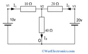
Consider the following circuit to determine the node voltages using nodal analysis with a voltage source. From the above circuit, O is the reference node, and V1, V2, and V3 are the voltages of non-reference nodes with respect to reference node O.
Since from the circuit, we know that V1= 10 Volts, V3 = 20 Volts.
The node voltage V3 can be calculated using Ohm’s law.
[(V1 – V2) /10 ]+ [(V3 – V2) /20] = V2 / 40
Substitute the values of V1 and V3 in the above equation,
(1- V2 / 10) + (1- V2 / 20) = V2 / 40
2= V2 (1/40 + 1/20 + 1/10)
V2= 80/7 Volts
To find the branch current I2, substitute the value of V2 in the V= IR equation
Then we get
80/7= I2 (40)
From the circuit resistance R = 40ohms
I2= 2/7Amps= 0.286 Amps.
The same value of current I2= 0.286 Amps can be obtained by using KCL.
Among the two techniques of mesh and nodal analysis in solving the circuit, the nodal analysis is simple and appropriate when there are a large no. of current sources around.
Example Problems
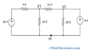
Nodal analysis example problems with a voltage source and current source are explained above with step by step procedure. Now let’s solve another simple circuit that consists of both voltage and current sources and find out the unknown node voltages and current across the resistor using nodal analysis. The nodal analysis example circuit is shown below.

Nodal Analysis Example
Step 1: assign and label the nodes as shown in the above circuit. There are 3 nodes with node voltages V1, V2 and V3. Where V3 is the reference node and V1 &V2 are non-reference nodes
Step 2: obtain the node equations to node 1 and node 2. Consider one node voltage is greater than other node voltages
The node equation to node 1 is written as,
[(V1 – 20) /5 ]+ [V1 / 10 ]+ [(V1 – V2) /10] = 0
(2V1 -40 + V1 + V1- V2) /10=0
V2= 4V1 – 40…….eq 1
The node equation to node 2 is written as
-4 + (V2 / 20) + [(V2 – V1) /10] = 0
(-80 + V2 + 2V2 – 2V2) /20 =0
After simplifying we get,
3V2 – 2V1= 80…..eq 2
Step 3: Determine the node voltages V1 and V2 from equations 1 and 2.
From eq 1, V2 = 4V1 – 40
Substitute the above equation in equation 2
Then,
3V2 – 2V1 = 80
3 (4V1 -40) -2V1 = 80
12V1 – 120 – 2V1 = 80
10V1 = 80 + 120
10V1 = 200
Therefore the node voltage V1 = 20 Volts.
Substitute the V1 = 20 volts in equation 1 to obtain node voltage V2
V2 = 4V1 – 40
V2 = 4(20) – 40 = 40
Therefore the node voltage V2 = 40 Volts
Hence the node voltages around the circuit are 20 Volts and 40 Volts.
The branch current across the resistor 20 Ohms is,
I = V2/R
I = 40/20
I = 2 Amps
The branch current across the resistor 10 ohms is,
I = V1/R
I = 20/10
I = 2 Amps.
Therefore current flowing through the resistors in the circuit is 2Amps. From the above nodal analysis examples, we can conclude that the number of node equations required to solve the circuit is equal to the number of assigned non-reference nodes to the given electrical circuit.
Know more about Kirchhoff Law.
Please refer to this link to know more about Nodal Analysis MCQs.
Thus, this is all about an overview of nodal analysis – definition, nodal analysis with a voltage source, nodal analysis with a current source, the difference between mesh and nodal analysis, nodal analysis examples, and problems. The main purpose of the nodal analysis is to determine the unknown voltage and current quantities between two or more nodes with less number of node equations. Here is a question for you, ” What are the advantages of nodal analysis?”.