Major companies such as Texas Instruments, PIC, ST, and others provide many microcontrollers with different features and prices. But when it comes to differentiating these microcontrollers based on features and form factor versus price, choosing the right MCU for application between them will be very difficult. However, in 2008, a Taiwan-based semiconductor company called Nuvoton which was spun off as a subsidiary of Winbond offered many useful cost-effective microcontrollers, cutting-edge microprocessors, and mixed-signal chips. It offers all the features, and specifications at a very affordable price. This is why Nuvoton series microcontrollers stand out for their low cost and high feature support during the development and production phase. In this article, we will discuss a high-performance nuvoton series N76E003AT20 microcontroller.
What is in N76E003AT20 Microcontroller?
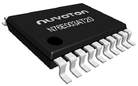
The N76E003AT20 is a 20-pin 8051-based MCU with 8-bit architecture and 18K flash memory and 18 I/O pins with special features such as I2C, UART, PWM with 6 channels, SPI, Brownout detectors, and wake-up functions. It belongs to the Nuvoton series microcontroller. It is equipped with a powerful CMOS processor of 16MHz and LDROM configurable to 0K/1K/2K/3K/4K bytes. These microcontrollers are useful for integrating into small applications and provide high system performance, reliability, and cost savings. Its operating voltage is an important feature, which makes this MCU suitable for large-scale applications.

N76E003AT20 Microcontrollers
The 20-pin N76E003AT20 MCU is easy to install and integrate for most logic-level applications operating from 2.4V to 5.5V. In terms of peripheral support, the N76E003AT20 is developed with 17 general purpose I/O pins and one additional pin only for input operations, two 16-bit timer/counters with standard 8051, SPI, two UART ports, I2C ports- one port each and support 500Kbps 12-bit ADC. For motor control tasks, the N76E003AT20 provides support for multi-channel PWM.
The N76E003AT20 is a high-speed MCU with a 16MHz oscillator, SPI, I2C, UART, self-wake-up timer, ADC, 6-channel PWM, and fault brake. It is widely used in consumer applications and moderate projects.
Pin Configuration:
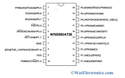
N76E003AT20 is a 20-pin microcontroller based on 8-bit 8051 architecture. It is available with 18kB of flash memory, 16MHz CPU, and a 0K/1K/2K/3K/4K bytes of LDROM configuration. The pin configuration of the N76E003AT20 microcontroller is shown in the figure below.

Pin Diagram of N76E003AT20 MCU
PWM2/IC6/T0/AIN4/P0.5: This is the I/O pin of bit 5 of port 0, PWM channel 2 or Input capture CH6 or counter/timer 0 of external count input, or analog input CH3.
TXD/AIN3/P0.6: This is the I/O pin of port 0 bit 6, serial port 0 transmits data output or Analog Input CH3.
RXD/AIN2/P0.7: This is the I/O pin of bit 7 of port 0, receive data input serial port 0 or Analog Input CH4.
RST/P2.0: This is the low Input pin Port 2 bit 0, and indicates the Schmitt trigger input pin for hardware reset.
INT0/OSCIN/AIN1/P3.0: This is the I/O pin of port 3 bit 0, Interrupt input pin 0, or Oscillator input or CH1 analog input pin.
INT1/AIN0/P1.7: This is the I/O pin of port 1 bit 7 or external interrupt 1 input, Channel 0 ADC input pin.
GND: This is the digital ground connection pin, which refers to 0V.
ICPDA/OCDDA/TXD_1/[SDA]/P1.6: This pin is the port 1 bit 6 or ICP input and output data or input-output OCD Data or serial port transmit data or I2C data pin.
VDD: This pin refers to the digital power supply connection to power the unit.
PWM5/IC7/SS/P1.5: This is the I/O pin port 1 bit 5 or PWM 5 or channel 7 input capture or SPI slave select input.
SDA/FB/PWM1/P1.4: This is the I/O pin of port 1 channel 4 or I2C data pin or fault brake input pin or channels 1 PWM output pin.
SCL/[STADC] /P1.3: This is the I/O pin of port 1 channel 3 or I2C clock pin or external start ADC Clear pin.
PWM0/IC0/P1.2: This is the I/O pin of port 1 bit 2 or PWM 0 pin or channel 0 input capture pin.
PWM1/IC1/AIN7/CLO/P1.1: This is the I/O pin of port 1 bit 1, channel 1 PWM pin or channel 1 input capture pin, or channel 7 analog input or System clock output pin.
PWM2/IC2/SPCLK/P1.0: This is the I/O pin port 1 bit 0, channel 2 PWM pins or channel 2 input capture or SPI clock pin
PWM3/IC3/MOSI/T1/P0.0: This is the I/O pin of port 0 bit 0, channel 3 PWM pin or channel 3 input capture or SPI Master input/slave input or Timer/counter 1 external input.
PWM4/IC4/MISO/P0.1: This is the I/O pin of port 0 bit 1, channel 4 PWM pin or channel 4 Input Capture or SPI Master input/slave output pin.
ICPCK/OCDCK/RXD_1/[SCL]/P0.2: This is the I/O pin of port 0 bit 2, ICP clock input pin or OCD clock input or serial port 1 receives input or I2C clock pin.
PWM5/IC5/AIN6/P0.3: This is the I/O pin of port 0 bit 3, channel 5 PWM pin or channel 5 Input Capture or channel 6 Analog input pin.
AIN5/STADC/PWM3/IC3/P0.4: This is the I/O pin of port 0 bit 4, channel 4 PWM pin, or channel 3 input capture or external start ADC trigger pin.
Note:
Analog signals are generated by PWM modulation channels;
- ICP (Input Capture Pin) for measuring pulses of timers.
- Serial communication ports for transmission of serial data are UART, MOSI (Master-Out-Slave-In),
- MISO (Master-In-Slave-Out), and I2C which includes SCL and SDA.
- A FB (Fault Brake) for providing motor control to the unit.
Features of N76E003AT20 Microcontroller:
The following are the features of the N76E003AT20 Microcontroller unit:
- It is a 20-pin CMOS based 8-bit 8051 microcontroller unit with a fully static design high-performance N76E003 series processor, compatible with an MCS-51 instruction set, 4-level priority interrupts, and DPTRs (dual data pointers).
- Width of the data bus- 8-bit.
- Operating voltage range- 2.4V to 5.5V.
- Operating clock frequency- 16MHz (maximum).
- Low-speed internal oscillator frequency- 10KHz.
- Size of APROM program memory- 18kB.
- Size of data RAM- 256 Bytes (On-chip RAM).
- LDROM configuration- 0K/1K/2K/3K/4KBytes.
- Flash memory accumulation for each page- 128 Bytes.
- Operating temperature range- -40°C to +105°C (industrial range).
- Resolution of ADC- 12-bit.
- Interface types- SPI, I2C (1), and UART (2).
- No. of ADCs- 1 contains 8 channels.
- 16-bit Timers/counters- 2.
- PWM channels- 5.
- PWM counter interrupts for the timer- 16-bit.
- Standard interrupt pins- 2 (INT0′ and INT1′).
- Data rate- 8Mbps for SPI and 400kBps for I2C.
- Power modes- Idle and power-down.
- Development tools- Nuvoton OCD (on-chip debugger) with KEIL software.
- Programming- IDE Keil-U-Vision and C51 compiler.
- Available in the TSSOP and SOP packages.
Block Diagram of the N76E003AT20 Microcontroller:
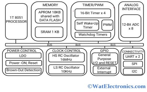
The N76E003AT20 is an 8-bit high-performance embedded flash-type microcontroller based on a 1T 8051 processor. The instruction set is completely compatible with the 80C51 standard, which enhances the performance of the MCU. The architecture or the block diagram of the N76E003AT20 microcontroller shown below gives an overview of its features and peripherals.

Block Diagram or Architecture of N76E003AT20 MCU
1T 8051 Processor
The N76E003AT20 MCU is an 8-bit based on CMOS 8051 processor with a fully static design and performance high. It has the capability of 4-level priority interrupts; dual data pointers (DPTRs) and an instruction set compatible with MCS-51. It has a frequency of a maximum 16MHz and the operating voltage range is 2.4V to 5.0V at -40°C to 105°C temperature range.
Memory
This MCU supports program memory APROM (stores instruction codes) of 18K Bytes to store user code and flash memory accumulated with pages of 128 bytes each. It provides data memory (stores data during program execution) SRAM of 1KB and On-chip RAM (internal RAM) of 256 Bytes. It supports configurable data flash LDROM of 0K/1K/2K/3K/4K bytes to provide user-developed boot code. Has built-in ISP, ICP, and IAP. It had a code lock for security purposes.
Timer/PWM
The N76E003AT20 microcontroller supports 6-channel PWM with 16-bit resolution (maximum) with programmable and duty. It is used to drive and control single-phase motors, 3-phase brushless DC motors, and 3-phase AC induction motors. When this is used in complementary mode, a programmable dead-zone generator will be available for the simultaneous protection of MOS turn-ON. The PWM signal is useful for control operations such as driving motors, controlling fans, LED lighting/dimming, digital to analog converter output simulation through LPF circuit, etc.
- This MCU provides two 16-bit timers or counters 0 and 1 compatible with the 8051 standards.
- The self-wakeup timer or general purpose timer provides the wake-up timer in low power mode. It is for reduced power modes.
- Supports one watchdog timer (WDT), which is programmable and configured as the time-out reset timer to reset the entire device. That means, in an abnormal state or if any interference occurs, this WDT resets and recovers the system.
- Programmable WDT is clocked with an internal oscillator of 10KHz.
- The 16-bit auto-reload timer is to set the baud rate clock source of UART.
- Supports one 16-bit PWM counter interrupt for the timer.
- One 16-bit timer with a 3-channel input capture module.
Analog Interface
The N76E003AT20 MCU supports 12-bit SAR ADC to convert analog input signals and represent that 12-bit binary signal. It provides 8-channel inputs and should be selected in single-end mode (input mode). It generates the digital output signal for the analog signal level through successive approximation and stores the result in registers.
The N76E003AT20 MCU supports one 12-bit ADC at a conversion rate of up to 500 kbps with hardware triggering and motor controlling facility.
Power Control
It controls and saves power consumption during the execution of the unit. This power control or power monitor prevents incorrect execution during power down mode and power on reset (POR) mode.
- The power ON Reset (POR) or power on detection is to detect the power up after the voltage reaches a certain level during the functioning of the unit.
- During the program execution, the brownout detection or low-power BOD monitors the voltage level and saves the power consumption periodically.
- In IDLE mode, the CPU of the MCU stops the clock and suspends the process/data by holding the program counter. But all the peripherals will be in an activated state. In this mode, the stack pointer, program counter, accumulator, program status word, and others register their data/content because the CPU will be in a frozen state.
- The power down mode/shutdown mode is the low power state of the device. That means it consumes low power and the CPU goes to low power mode, stops peripherals and clock, and the program counter suspends their content. The CPU and the peripherals work like either timers or UART.
- There are several ways to bring the N76E003AT20 out of power-down mode. Firstly, it resets all resets except software reset. A Brown-out reset brings the processor/CPU out of power-down mode. Make sure Brown-Out Detection (BOD) is enabled before the system goes into power-down mode. However, it is recommended to turn ON the low-power BOD in the power-down mode for the lowest power consumption. Of course, the reset state is released (removes the power-on reset status) by resetting the external pin and performing a power-on reset. After the external pin reset or power-on reset, the processor is initialized and starts executing the program code from the very beginning.
Clock Control
The clock control is utilized to enhance the performance and minimize the power consumption of the N76E003AT20 MCU. It is embedded with two internal oscillators (at <±2% deviation at all conditions) like Low-Speed (LS) 10KHz and High-Speed (HS) 16MHz RC oscillators. It also provides one external clock input. Both the LSRC and HSRC oscillators are enabled as the system clock. But by default, the HSRC is selected as a system clock and LSRC is enabled when the unit is powered up.
GPIO
This MCU has 17 general-purpose I/O pins and one Input-Only pin (Reset pin). While all the output pins have 2-level slew rate control. Supports two external standard external interrupts (INT0)’ and (INT1)’ used to release the CPU from the power down mode and start the execution.
Connectivity
The N76E003AT20 microcontroller supports two enhanced full duplex serial ports with framing error detection and address recognition capability. Each serial port supports communication in synchronous mode and 2 modes in full-duplex UART up to 115200 bps.
- It supports one full duplex serial peripheral interface (SPI) serial communication in full duplex and provides a synchronous communication bus between the MCUs or other peripherals like serial EEPROM, ADC, LCD driver, etc. It provides either master or slave mode in high speed up to 8 Mbps at 16MHz.
- It supports one Inter-Integrated Circuit (I2C) of up to 400 Kbps for serial bus interface between the MCUs and the I2C devices like temperature sensors, LCD modules, EEPROM, etc. The data transfer between the master and slave is bi-directional.
Please refer to this link for : Interfacing ADC Peripheral with N76E003AT20 Microcontroller.
How to Program N76E003AT20 Microcontroller?
Programming the Nuvoton N76E003AT20 MCU requires an IDE (Integrated Development Environment) and a C51 compiler. You can program these 8051-based microcontrollers using various programs and compilers available on the market, but Keil Vision is the most popular IDE that comes with the C51 compiler for programming 8051-based microcontrollers. A compiler converts your program into a readable MCU format is called a HEX file. Hence, Programming N76E003AT20 MCU requires,
- Keil u-vision IDE
- C51 Compiler.
However, Keil u-vision is not available for free. But the free version is widely used for most important tasks.
Applications
A few applications of the N76E003AT20 microcontroller are given below.
- Data acquisition systems.
- In low-power embedded systems.
- Low-cost sensor integration.
- Data retention/collection applications (small data).
- Access control systems.
- Thermostat.
- Bluetooth speaker.
- Battery chargers.
- Small home appliances.
- Beauty equipment.
- Electric meters.
- Audio controllers.
- Data access controls.
Please refer to this link for 24LC1026 Serial EEPROM.
Please refer to this link to know more about N76E003AT20 Microcontroller Datasheet.
Thus, this is all about the N76E003AT20 Microcontroller – features, pin configuration, programming software, and applications. The alternatives are AT89LP2052, AT89C2051, and N76E003AS20. Many parameters like operation voltages, analog voltage readouts, and communication protocols are considered before choosing an N76E003AT20 microcontroller for your project. For example, for sensor and actuator-based projects, an N76E003AT20 microcontroller with sufficient ADC channels and resolution should be used.