When a conventional geared DC motor is connected directly to the output of the ICs such as Atmega16, microcontrollers, 555 timers, and 74 series ICs the motor might get damaged. Because these ICs cannot provide at least 250mA of current required for the DC motor. Therefore, to drive the DC motor, a circuit (with transistors or relays or L293D/L298) is needed that can work as a bridge between the motor and the IC. Hence, the manufacturers and hobbyists use several IC motor driver modules in projects such as MX1508 L298, L293, TB6612, and L9110. The MX1508 DC motor driver module is affordable and widely used to drive motors in toy cars and other devices. This article gives a brief description of the MX1508 DC driver module in detail.
What is an MX1508 DC Motor Driver?
A cost-effective motor driver module with integrated 2 H-channel driver circuits designed with P-channel and N-channel MOSFETS is called MX1508 DC motor driver. It can drive DC stepper motors up to 2A rating. It is suitable for controlling engines in toy cars and other applications. This module is also equipped with an internal thermal protection circuit and a common line circuit to prevent damage to the motor if the input contacts are left ungrounded (floating). The MX1508 IC has an operating voltage of 1.8V to 5V but can drive a motor with an operating voltage of 2V to 9.6V.
Pin Configuration of MX1508:
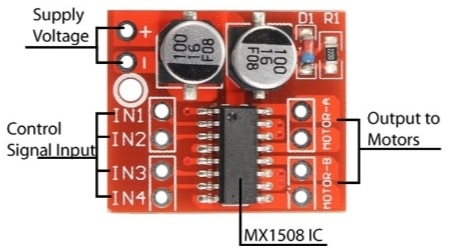
The MX1508 DC motor driver is available in an 8-pin module with 2 pins for power supply, 2 motor output pins for connecting and controlling 2 motors simultaneously, and 4 input pins for controlling output obtained from the external circuit like Arduino and microcontroller. The pin configuration of MX1508 is explained below.

MX1508 DC Motor Driver
- Pin1: + or Vs pin: It refers to the input supply voltage of 2 to 10V to power up the module.
- Pin2: – or GND pin: It refers to the common ground connection for a module and external circuit.
- Pin3: IN1 pin: It refers to the control input signal 1 of motor A.
- Pin4: IN2 pin: It refers to the control input signal 2 of motor A.
- Pin5: IN3 pin: It refers to the control input signal 3 of motor B.
- Pin6: IN4 pin: It refers to the control input signal 4 of motor B.
- Pin7: Motor A: It refers to the output pins connected to motor A.
- Pin8: Motor B: It refers to the output pins connected to motor B.
Features of MX1508 DC Motor Driver
The feature of the MX1508 DC Motor Driver Module is,
- MX1508 is a dual H-bridge DC motor driver with P-channel and N-channel MOSFETs used to drive 2 DC motors or 2-phase 4-wire stepper motors.
- Designed in common conduction mode.
- Built-in common linear circuit. If the input pin is left floating, the motor will not run.
- Built-in thermal protection circuit with hysteresis effect (TSD), without worrying about turning off the motor. > Super small size.
- It is a dual H-Bridge PWM DC Stepper Motor Driver Module ideal for use in battery-powered toy cars, smart cars, toy cars, and robots.
- It can drive two DC motors or 2-phase 4-wire stepper motors,
- It can control forward or reverse rotation, and speed.
- It provides thermal protection and automatic recovery.
Technical Specifications of MX1508
The following are the technical specifications of the MX1508 DC motor Driver Module,
- It is an integrated dual H-bridge motor driver with in-built flyback diodes and capacitors to avoid EMF reverse voltage spikes.
- The MX1508 module requires a supply voltage of 2V to 10V.
- The Signal input voltage is 1.8V to 7V.
- The signal operating current is 1.5Amps.
- Peak current is up to 2.5Amps.
- Standby current is low : >0.1micro amps.
- Quiescent operating current is low.
- The diameter of the mounting hole is 2mm.
- The length is 24.7mm.
- The breadth is 21mm.
- Height is 5mm.
- Weight is 2gms.
- Shipment weight is 0.005kg.
- Shipment dimensions are 8x6x1cm.
- Motor Switching frequency: 50Hz.
- Available in SOP16 package.
Circuit Diagram Of MX1508 DC Motor Drive Using H-Bridge Connection:
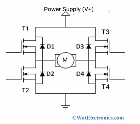
The MX1508 does not have a blocking/flying diode, to control the huge power surges on power lines and other problems that occur in connected devices/components caused during the rotation change. Therefore, a motor is connected on the right side of the H-bridge. The basic circuit diagram that illustrates the working of the MX1508 DC driver module with dual H-bridge connection using P-channel and N-channel MOSFETs and free-wheeling/flyback diodes is shown in the figure below.

MX1508 Circuit Diagram H-bridge Configuration
As shown in the above circuit diagram, the 4 switching elements and the load at the center form an H-bridge configuration. The switching elements are T1, T2, T3, and T4, which are FETs Or bi-polar transistors that turn ON and OFF independently. The flyback diodes are D1, D2, D3, and D4, which are generally Schottky diodes used to protect the circuit from voltage surges and polarity inversion of the supply. The battery is connected to the supply and also the bottom of the circuit is grounded.
The operation of the circuit is simple and easy. When the transistors T1 and T4 are turned ON, the left side of the DC motor is connected to the positive power supply and the right side of the motor is connected to the ground. Therefore the current flow through the motor energizes and starts rotating in forwarding or clockwise direction (the motor’s shaft spins forward).
When the transistors T2 and T3 turn ON, the left side of the motor is grounded and the right side of the motor is connected to the power supply. Hence the current starts flowing to the motor and gets energized to run in reverse or anticlockwise direction (the motor’s shaft spins backward).
When the transistors T1 and T2 are ON Or T3 and T4 are ON at the same time, the low resistance path is generated from the power supply to the ground. This results in a short circuit of the power, which is called a shoot-through condition, and the motor or the whole bridge circuit might get damaged. So, this state of transistors is avoided.
How to Use MX1508?
This section explains how to use the MX1508 DC motor driver module by using the Arduino UNO board. As we know, the MX1508 is a low-cost dual H-bridge motor driver PWM control mini motor module used for battery-powered toy cars, smart cars, robots etc. The major drawback of this motor driver is the need for PWM pins. One motor requires two PWM pins. So, instead of using 2 PWM pins, we can use 1 PWM pin (here pin is taken) and any one digital pin (pin 8) of the Arduino UNO. Hence, the response of the motor in one direction is different from the response of the motor in the other direction (fast and slow). It is possible to change the PWM resolution by using 16-bit PWM with pins 9 and 8 PWM on the Arduino Nano/Uno. Theoretically, the value can range from 0 to 65535. Otherwise, we can use 2 PWM pins (3/5/6/9/10/11 pins) of the Arduino UNO as per the application requirement.
Motor A and Motor B used for connecting 2 DC motors at a time to run simultaneously and provide a maximum current of 2 Amps. It operates at a temperature of 15°C.
The components required for MX1508 DC motor driver module interfacing with Arduino UNO are
- Arduino UNO R3.
- MX1508 Motor Driver module.
- 9V DC Motor.
- Battery (2-10V) for supply.
- Jumper wires for connection.
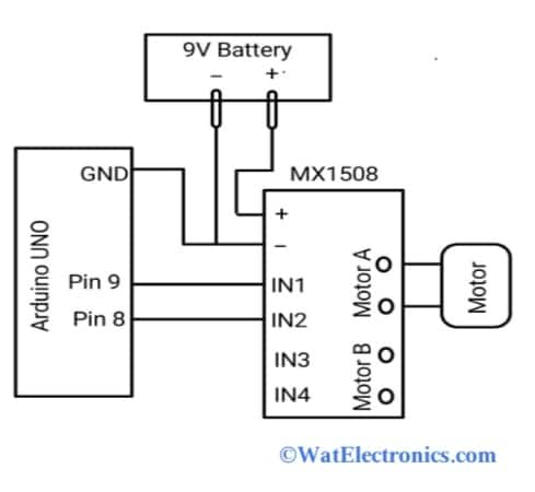
The interfacing circuit diagram of the MX1508 module with the Arduino UNO is shown below.

Interfacing MX1508 with Arduino
Connections are made as per the above circuit diagram. The voltage input pin (+) and ground (-) pin of the MX1508 module is connected to the positive terminal and negative terminal of the battery. The motor A pins of the MX1508 module are connected to the motor DC terminals as shown in the figure.
The GND pin of the Arduino board is connected to the ground pin (-) of the MX1508 module. Pins 8 and 9 of the Arduino board are connected to the IN2 and IN1 pins of the MX1508 module. The motor A output pins in the module are connected to the motor to control the rotation direction of the motor. Pin 8 and Pin 9 are the PWM o/p pin of the Arduino UNO.
Upload the Arduino code as shown below to run the motor in forward and reverse directions.
void setup() {
pinMode(8, OUTPUT); //IN2
pinMode(9, OUTPUT); //IN1
}
void loop() {
// Full speed forward
digitalWrite(8, HIGH);
digitalWrite(9, LOW);
delay(5000);
// Full speed backward
digitalWrite(8, LOW);
digitalWrite(9, HIGH);
delay(5000);
// 0 to 100% speed in forward mode
for (int i=0;i<256;i++)
{ digitalWrite(8, HIGH);
analogWrite(9, i);
delay(20);
}
delay(50);
// 0 to 100% speed in backward mode
for (int i=255;i<0;i–)
{ digitalWrite(8, LOW);
analogWrite(9, i);
delay(20);
}
delay(50);
}
From the above Arduino code, first, the motor runs in a clockwise (forward) direction for 5 seconds and then in an anticlockwise (backward) direction for another 5 seconds. Then the motor stops running and then increases its speed from 0 to 100 percent to run in a clockwise direction at a constant acceleration. Similarly, it runs in an anticlockwise (reverse) direction.
The following truth table shows how to run motor A in a forward or reverse direction by controlling the input signals 1 and 2 (IN1 and IN2).
|
IN1 |
IN2 |
Motor Rotation |
|
L |
L | The motor doesn’t run |
|
H |
L | Forward rotation |
| L | H |
Reverse rotation |
| H | H |
Brake |
To drive and control the other motor the same procedure is followed by connecting the Motor B pins of the module to the selected motor. Therefore two DC motors can be controlled independently and simultaneously.
Applications/Where to Use?
The MX1508 DC motor driver module is used in a few applications such as,
- Drives high-current LEDs.
- Drives 2-phase stepper motors.
- Drives two independent DC motors simultaneously.
- Applicable as relay driver module.
- Drives the 2 DC motors in forward and reverse directions.
- Used in battery remote-controlled toy cars, smart cars, robots, and other devices.
know more about the Motor Driver and Microcontroller.
Please refer to this link to know more about the ULN2003 Motor Driver IC.
Know more about TB6600 Stepper Motor Driver.
Thus, this is all about an overview of the MX1508 dual H-bridge DC motor driver module. The alternatives of the MX1508 DC motor driver module are L293D, L298N, SmartElex 15S, VNH3ASP30, VNH2SP30, and TB6612FNG. It is also known as an integrated dual H-bridge PWM speed stepper motor driver and dual L298N channel DC motor driver board.