The MJE13005 is a high-voltage & high-speed power transistor that belongs to the family of NPN transistors. The MJE13005 transistor is a semiconductor device that is made up of silicon (Si) material. This transistor is a current-controlled device that includes three terminals; an emitter, base, and collector. This transistor supports loads up to 4A & the voltage from the emitter base is 9V which is the necessary voltage for transistor action. This article provides brief information on the MJE13005 Transistor, pin configuration, specifications & its applications.
What is MJE13005 Transistor?
The MJE13005 is a high-power NPN that is mainly used for switching as well as amplification purposes. This transistor has three layers where one layer is P-doped & other two layers are N-doped. The layer with P-doped stands in between two N-doped layers. The three terminals of this transistor carry different doping concentrations because the collector pin doping concentration is light, emitter pin’s doping concentration is high as compared to the other two transistor terminals.
The base pin is doped ten times more as compared to the collector pin. Furthermore, the entire current of the device is carried out at the emitter terminal side because the sum of both the base & collector current is the emitter current. The collector-to-emitter voltage of this transistor is high – 400V with 4A of constant collector current. This NPN Transistor has an extremely low fall time so it is appropriate for AC voltage switching for inverter & converter applications.
Pin Configuration:
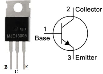
The pin configuration of the MJE13005 Transistor with its symbol is shown below. This transistor includes three terminals and each pin functionality is discussed below.

MJE13005 Pin Configuration
Pin-1 (Base): This pin is used to control the transistor biasing by turning ON/OFF the transistor.
Pin-2 (Collector): The current flows throughout the collector and this pin is connected normally to the load.
Pin-3 (Emitter): The current drains out throughout this terminal and this pin is connected normally to the ground.
Features & Its Specifications:
The features and specifications of the MJE13005 transistor are discussed below.
- It is a high-voltage transistor.
- It is an NPN-type transistor.
- It is available in the TO-220 package.
- Its switching speed is high like; 0.9uS.
- Its DC current gain or hFE is 8 to 40.
- Its maximum base current is 2A.
- Its continuous collector current or IC is 4A.
- Its emitter to base voltage or VBE is 9Volts.
- Its collector-to-emitter voltage or VCE is 400 Volts.
- Its maximum transition frequency or fT is 4 MHz.
- Its collector to base voltage is VCB is 700V
- Its maximum collector dissipation or Pc is 75 Watts.
- Its maximum operating and storage temperature must be from -65 Centigrade to +150 Centigrade.
Equivalent MJE13005 transistors are:
MJE13007, 2SC3795 and KSE13007 whereas other NPN type power transistors are; BD139, 2N3055, 2SC5200, MJE13001 & TIP31C.
How to use a MJE13005 Transistor securely in a Circuit?
To use an MJE13005 transistor securely within a circuit for a long time, it is suggested not to use this transistor to its maximum limits but it is better to utilize it a minimum of 20% under its maximum ratings. Do not drive any load from 3.2A-3.5A because its max load current is 4A. The highest load voltage is 400Volts thus always stays approximately 300V-320V DC. Always utilize an appropriate heat sink by this transistor. This transistor needs to operate and store in temperature that ranges from -65 to +150 Centigrade. Connecting a resistor to the base terminal of the transistor prevents it from frequent damage. Read on Choosing Base Resistance for Transistors in Electronic Circuits to know more about it. In case if it necessary to replace this transistor with its equivalents then read on Replacing Transistors in Electronic Circuits: Factors and Considerations.
Simple Inverter Circuit with MJE13005 Transistor
An inverter is an electrical circuit used to change the DC into an AC like; 4V DC – 220V AC. These circuits are broadly used within electronic circuits of tiny gadgets to different electronic devices. Here we are going to make a very simple inverter circuit that is very helpful for beginners to know the procedure. This inverter circuit is very easy to design & also to use within various electronic devices.
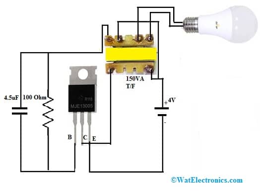
The required components to make this inverter circuit mainly include; a MJE13005 transistor, 10 ohm to 100-ohm resistor, connecting wires, a 4.5uF capacitor, a 150VA transformer, and a 4V battery. Connect the circuit as per the circuit shown below.

Simple Inverter Circuit with MJE13005 Transistor
Working
This circuit working is very simple. The primary component used in this circuit is a 150VA transformer. This transformer can be taken from old mobile phone chargers. Although not all the transformers of mobile phones are the same. So we should verify the transformer before connecting to the inverter circuit.
Once the circuit connections are made according to the above circuit diagram, and then provide 4V DC power to the circuit. The MJE13005 transistor performs the high-speed switching.
Here, this transistor’s base terminal simply controls the transistor biasing & the emitter terminal of this transistor is connected to the ground so that it drains out the flow of current. Therefore, the current supplies throughout the collector terminal and is directly connected to the 150VA transformer to step up the DC voltage. Consequently, this transformer in the inverter circuit drives the simple inverter circuit’s load.
The applications of this simple inverter circuit mainly include; lightning systems, indicator circuits that utilize AC power, AC circuits, kitchen appliances, mixers, conveyors, televisions, power tools, etc.
Applications
The applications of the MJE13005 transistor are discussed below.
- MJE13005 transistors are suitable mainly for 115 & 220V switch mode applications like; inverters, switching regulators, deflection circuits, motor controls, etc.
- The MJE13005 transistor is the perfect choice within high-speed high voltage switching circuits mainly for inverter & converter applications.
- This transistor can also be used within solenoid or simple relay driver circuits due to its capability to handle upto 8A of peak current.
- These transistors are normally used in SMPS designs with a switching transformer for switching 115V/220V AC voltage at high frequencies.
- These transistors are used in DC to DC converters, motors speed control, etc.
- This transistor has 75W collector dissipation so it is perfect to use within audio amplifier circuits.
- Even though this type of transistor is built for high voltage-based applications it can be used as an amplifier/switch within low voltage & battery operated based circuits.
- This transistor is used in different high-voltage applications like motor controllers, UPS, high-voltage-based power supplies, battery chargers, and many more.
- This transistor is used in stages to design high-power amplifier
- It can be used as a separate amplifier for driving a speaker.
Before using any of the transistors first we need to know how to choose a transistor for a circuit. Click this link How to Select a Transistor to know about it and transistors can be interface to a microcontroller. Check on this link to see how interfacing a transistor to microcontroller.
A few precautions need to be taken before connecting it to the microcontroller. Click on the link to know more about it: Precautions to be taken before connecting a transistor to the microcontroller.
Please refer to this link for the MJE13005 transistor Datasheet.
Thus, this is an overview of an MJE13005 transistor, pin configuration, features, specifications, circuit, working, and applications. The MJE13005/13005 transistor has 0.9uS of switching speed, so it is the perfect choice for high-speed switching and high-voltage circuits wherever the switching speed is significant like inverters & also converters. Here is a question for you, what is 2SC3795 transistor?