Li-ion battery charger is an integrated circuit that regulates battery charging voltage and current used in portable devices like; laptops, tablets & cell phones. Compared to other battery charger ICs, Li-ion batteries contain the highest energy densities, providing a high voltage per cell to tolerate high currents. Additionally, Li-ion batteries do not include a memory effect, so they do not consider a low charge ability if they are completely charged before depleting. But, Li-ion batteries should be charged through a specific constant current & constant voltage charge profile that is adjusted automatically based on the temperature & voltage levels of the battery. This article provides brief information on MCP73831 IC, pinout, specifications, and its applications.
What is MCP73831 IC?
The MCP73831 ICs are advanced linear charge management controllers, used in cost-sensitive and space-limited applications to charge Li-ion or Li-Po batteries by providing an efficient and simple solution. These ICs can also be known as small single-cell and fully incorporated Li-Ion Li-polymer charge management controllers. This battery charger IC is available in packages like 8 terminal DFN package (or) a 5-terminal SOT-23 package. These ICs use a constant current (or) constant voltage charge algorithm through selectable preconditioning & charge termination.
The constant voltage regulation can be fixed through four options 4.20Volts, 4.35Volts, and 4.40Volts (or) 4.50Volts to contain new and emerging battery charging requirements. The MCP73831 IC limits the charge current depending on die temperature in high ambient or high power conditions. So the thermal regulation enhances the charge cycle time by maintaining the reliability of the device. There are many options available for the preconditioning threshold, current value, automatic recharge threshold, and charge termination value.
Working
The MCP73831 IC works as a dedicated Li-ion battery charger by providing a stable current followed by a constant voltage charge until the battery attains full capacity. This IC starts the battery charging with a stable current and, after that transitions to a stable voltage phase when the battery attains a pre-set voltage of normally 4.2Volts for Li-ion batteries.
This IC can also monitor its temperature and adjusts automatically the charge current to avoid overheating in high-power charging situations. So based on the specific variant of this IC, you can select the precise charge termination voltage to suit various types of batteries.
The power source like a USB adapter or a solar panel is connected to the MCP73831 IC input pin. For current sensing, a small resistor can be arranged in series by the battery after that, the voltage drop across the resistor can be monitored to decide the charging current through the IC.
This IC adjusts the delivered power to the battery to maintain the preferred charging profile depending on the voltage & current of the battery. So, MCP73831 IC variants can have a status pin that signals whenever the battery is charged fully or any fault condition is there.
MCP73831 IC Pin Configuration:
The MCP73831 IC pin configuration is shown below. So this IC includes five pins which are discussed below.
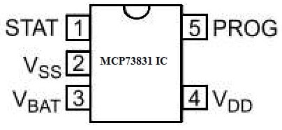
MCP73831 IC Pin Configuration
- Pin-1 (STAT): It is a charge status output pin that acts high in the charge cycle.
- Pin-2 (VSS): It is a GND pin that is connected to batteries negative terminal & input supply.
- Pin-3 (VBAT): It is a battery charge control output pin that is connected to the batteries +ve terminal.
- Pin-4 (VDD): It is a battery management input supply, so it provides an input voltage supply for the charge controller.
- Pin-5 (PROG): It is a charge current programming pin that is connected to a resistor to the ground for setting the charge current.
Features & Specifications:
The features and specifications of MCP73831 IC include the following.
- MCP73831 IC is a linear charge management controller with a pass transistor, current sense, and reverse discharge protection.
- The mounting style is SMD/SMT.
- The package/case is SOT-23-5.
- Its high accuracy preset voltage regulation is + 0.75%.
- It has four voltage regulation options are; 4.20V, 4.40V, 4.35V, and 4.50V.
- Programmable charge current ranges from 15 mA to 500 mA.
- Selectable preconditioning is 10%, 20%, 40% (or) disabled.
- Its selectable end-of-charge control is 5%, 7.5%, 10%, (or) 20%.
- It is manufactured by microchip technology
- The series is MCP73831/2.
- The product type is battery management.
- Battery type: Li-Ion or Li-Polymer.
- Its output voltage is 4.2 Volts.
- Output current ranges from 15 mA to 500 mAmps.
- The operating voltage supply ranges from 3.75 V to 6 V.
- Operating temperature ranges from – 40°C to + 85°C
Equivalent & Alternative ICs
Equivalent MCP73831 ICs are; TPS62A02DRLR, MAX17260SETD+T, MCP6002T-E/MC, PIC24FJ128GL406-E/PT, MIC94043YFL-TR, IS31FL3199-QFLS2-TR, etc. Alternative battery charger ICs are; TP5100 module, TP5000, TP4056, etc.
Battery Charger Circuit with MCP73831 IC
Battery charger is one of the most significant types of electronic circuits utilized within portable modern electronic products particularly those for recharging lithium-polymer and lithium-ion batteries.
The most common battery chargers used at present are; MCP73831, BQ24092, and BQ24703. But the first two battery chargers MCP73831 & BQ24092 are linear chargers while the BQ24703 is a switch-mode buck charger. Linear regulators are capable of stepping down a voltage while the switching regulators are used to both step up and step down a voltage.
Here, we are reviewing the primary battery charger from the Microchip like MCP73831. So this is mainly designed to charge a solo cell which is designed for either lithium-polymer or lithium-ion batteries.
The battery charger circuit with MCP73831 IC is shown below. So a single lithium battery cell outputs approximately 3.6 V. If you observe a lithium battery through a 7.2 V rated output voltage it is made with two cells that are connected in series. If the voltage of the battery is 14.4 Volts then it is a four-cell battery pack.
To charge multi-cell-based battery packs then you should have either an input voltage supply that is above the battery charging voltage otherwise you require a switch-mode boost charger that produces a charge voltage above the input supply.
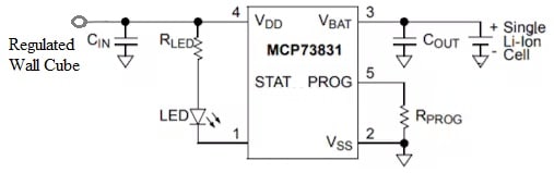
Battery Charger Circuit with MCP73831 IC
Working
This circuit works in three stages to charge a lithium battery which include; the pre-charge, the fast-charge stage & the charge termination stages. The circuit in the first two stages regulates the amount of current flowing into the battery whereas in the final charge termination stage, the charger changes the voltage supplying to the battery when the current supplying into the battery is measured which is explained below.
Pre-Charge Stage
The pre-charge stage is the first stage which is also called the trickle stage. So the battery charger in this stage sends a small amount of current into the battery only. If a battery is noticed, then the charger will start the charging procedure. The main goal of this pre-charge stage is to charge the lithium battery up to a certain level so that it charges quickly within the subsequent phase.
So the charger automatically moves into the pre-charge stage whenever a battery is discharged highly and with a below voltage of a certain threshold. When the pre-charge is in progress, then the battery voltage can be monitored through the charger until the pre-charge voltage threshold is attained.
So this is a predefined percentage of the highest charge current that you are liable for programming. When the battery voltage goes beyond the pre-charge voltage threshold, then the battery charger moves into the next stage.
Fast-Charge Stage
The fast-charge stage is the second stage which is called the constant current stage. So this stage changes the amount of current supplied into the battery. Here both the pre-charge & fast-charge currents can be set through a single resistor above the PROG pin of the IC.
The constant current can be utilized to charge the battery and is controlled depending on the highest charge current you have chosen. So, the maximum charge current for this IC can be set by connecting a resistor from the program pin to GND. You can choose a charge current from 15 mA to 500 mA. When the battery is close to being charged throughout this fast-charge stage then it switches to the final stage.
Charge Termination Stage
This is the final stage of charging, known as the constant voltage stage. So the battery charger in this stage switches into a voltage-controlled mode, wherever it changes the voltage supplying into the battery in place of the current.
Although the voltage toward the battery is being regulated, the charger checks the charging procedure by measuring the charge current. When the charge current within voltage-controlled mode reduces under a predefined percentage of the programmed current, then the charger identifies that the battery is completely charged & its procedure will be terminated.
The battery charger continuously monitors the battery voltage after the charge cycle is completed. If the battery voltage reduces under a pre-set recharge threshold, then the charger will start a new charge cycle & the entire process replicated.
Power Dissipation
The power dissipation is a significant factor when working through battery chargers, particularly MCP73831 linear battery chargers. These are not very efficient in certain circumstances but are essential whenever the charger does not overheat. Otherwise, the charging current will be reduced automatically under the preferred level to maintain the temperature above the maximum.
Power dissipation within a linear charger can be decided based on the load current and voltage disparity from i/p to o/p. The highest power dissipation and the probability of overheating normally occur whenever changing from the pre-charge to the fast-charge phase. To decide how much your charger heats, then the following equation is used.
Temperature Gain = Dissipated Watts x Theta-JA
The above equation informs you how much this IC heats beyond the ambient air temperature. So you should add the ambient air temperature to the above equation to obtain the absolute temperature.
So most electronic components are specified up to 125 C. Always avoid exceeding this temperature otherwise the charger will reduce the charge current as necessary to keep the temperature below 125C.
Difference between MCP73831 and MCP73832 ICs
The difference between MCP73831 and MCP73832 ICs includes the following.
|
MCP73831 |
MCP73832 |
| MCP73831 IC is a very advanced linear charge management controller. | MCP73832 is a battery charging controller IC. |
| Its package or case is SC-74A and SOT-753. | This IC is available in SC-74A and SOT-753 packages or cases. |
| This IC output current is 500mA. | Its output current is 10mA. |
| Its maximum output voltage is 4.232V. | The maximum output voltage is 4.5V. |
| Its max i/p voltage is 3.75V. | Its max i/p voltage is 6V. |
| This IC includes a push-pull output (or) it can drive LEDs directly. | This chip includes an open-drain output. |
Advantages & Disadvantages
The advantages of MCP73831 IC include the following.
- The MCP73831 IC is small and needs few external components, thus used in portable applications.
- The MCP73831 IC meets all the specifications mainly for USB power bus charging.
- It restricts the charge current depending on the die temperature to enhance the charge cycle time & maintain device reliability.
- This IC includes four options for stable voltage regulation; 4.20V, 4.50V, 4.40V, or 4.35V.
- The MCP73831 ICs are completely specified above the -40°C to +85°C ambient temperature range.
- It limits the charge current depending on die temperature in high power (or) high ambient conditions.
The disadvantages of MCP73831 IC include the following.
- These ICs cannot work at a high voltage.
- These are usually delicate and they cannot withstand a high-voltage operation.
- This IC has a limited power rating.
- It can generate more noise in operation.
- If components are overheated or damaged, then the charging process may change.
- This IC has limited input & battery voltage range, extreme power dissipation, high relative current consumption, lower relative efficiency & restricted charge termination algorithms.
Applications
The applications of MCP73831 IC include the following.
- The MCP73831 IC is used in charging Li-ion & Polymer batteries.
- The MCP73831 chip provides stable current charging with automatic charge termination.
- This IC restricts the charge current depending on the die temperature in high power (or) high ambient conditions.
- This IC outputs the charge status as output through LEDs.
- This advanced linear charge management controller is used in space-limited and cost-sensitive applications.
- It is used in MP3 players, USB chargers, digital cameras, cellular telephones, personal data assistants, Bluetooth headsets, etc.
Please refer to this link for the MCP73831 IC Datasheet.
Thus, this is an overview of MCP73831 IC which plays a key role in managing the charging procedure by ensuring secure and very efficient power delivery toward the battery. The examples of battery charger ICs are; TP4056, TP5100, TP4057, TP5000, MAX1555, MCP73831, MAX1898, LTC4054, etc. There are some important considerations while evaluating these battery charger ICs like; maximum charge current, efficiency, compatibility, charge termination voltage, temperature monitoring, voltage and current regulation, etc. Here is a question for you, what is TP5100 IC?