A DC-DC converter is an electronic circuit used in modern power management systems. So this circuit converts the level of the DC voltage source to another by ensuring efficient and stable power delivery to various electronic systems wherever input voltage levels can change because of factors like battery discharging eventually (or) changes within load conditions. The main benefit of these converters is their better power conversion efficiency. So they offer the flexibility to step down or up voltage levels by allowing efficient power distribution management in electronic systems. These can also provide galvanic isolation by separating the input & output grounds to decrease the risk of GND loops and protect sensitive components from noise and voltage spikes. This article elaborates on DC-to-DC converter ICs like MC34063 IC, pinout, working, and its applications.
What is MC34063 IC?
The MC34063 is a DC/DC converter IC in an 8-pin SOIC or DIP package. This IC was designed for voltage-inverter converter, buck, or boost applications for voltage boost and reduction. These ICs include a comparator, internal temperature compensated reference, controlled duty cycle oscillator through an active current limit circuit, driver & high current o/p switch. This IC can also have all the required blocks to design DC voltage converters, and it supports switched frequencies upto 100 kHz. So it is a very popular IC in DC/DC converter circuits due to its voltage conversion abilities, low cost & easy design.
MC34063 IC Working
The MC34063 IC is a monolithic control circuit, that designs DC/DC converters with minimum external components. This IC includes an internal temperature-compensated reference, a comparator, a controlled duty cycle oscillator through an active current limit circuit, a driver, and a high current output switch. This IC can change the output voltage, use low standby current, and limit short-circuit current so used in boost, buck, or voltage-inverter converter-based applications.
These ICs can be used to build converters in buck, boost, and inverting topologies. In Buck topology, it generates a voltage that decreases relative to the input voltage It generates a voltage in Boost topology, that is improved relative to the input voltage. Thus, the MC34063 IC can be used within an inverting topology to design a DC-DC converter:
Thus, MC34063 IC has a 3V to 40V wide input supply range which generates a 1.5A high output switch current by adding a suitable inductor. This IC can also provide short circuit current limiting, adjustable output voltage & a low standby current.
MC34063 IC Pin Configuration:
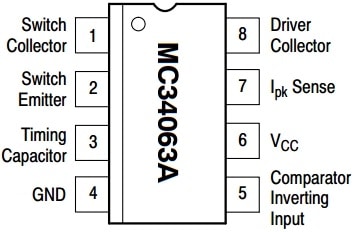
The pin configuration of MC34063 IC is shown below. This IC includes 8 pins which are explained below.

MC34063 IC Pin Configuration
- Pin-1 (Switch Collector): It is a collector pin of inside transistors which is also known as an o/p voltage pin.
- Pin-2 (Switch Emitter): It is an emitter pin of inner transistors.
- Pin-3 (Timing Capacitor): This pin decides the switching frequency.
- Pin-4 (Ground): It is a negative terminal of the power supply.
- Pin-5 (Comparator Inverting Input): This pin sets the output voltage.
- Pin-6 (VCC): It is an input voltage pin.
- Pin-7 (Ipeak Sense): This pin sets the o/p current.
- Pin-8 (Driver Collector): It is a collector pin for switching transistors.
Features & Specifications
The features and specifications of MC34063 IC include the following.
- MC34063 is a DC-DC converter IC.
- This converter IC includes 8 pins.
- Its input voltage ranges from 3V to 40V
- Its output voltage is adjustable and ranges from 1.25V to 40V.
- Its maximum current capacity is 1.5A.
- The switching frequency is 100 KHz
- The driver collector current is 100mA
- Its precision internal reference is 2%
- These ICs are BFR, Pb, and Halogen Free.
- These ICs are compliant with RoHS.
- Its operating temperature ranges from 0°C to 70°C.
- Its storage temperature ranges from −65°C to 150°C.
MC34063 IC Structure
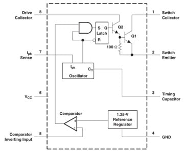
The MC34063 IC internal structure diagram is shown below. So the oscillator in this IC charges & discharges the timing capacitor continuously. This capacitor is connected externally to the CT and is connected to the pin-3 of IC through a constant current source, so producing an oscillation waveform. Whenever the load stays stable, then both the charging & discharging currents are stable. The oscillation frequency at this time depends only on the ability of the external timing capacitor.
The AND gate’s one end in the above figure is connected to the oscillator’s output. Whenever the oscillator’s external charge attains a certain threshold level, then the output of the oscillator will flip to a higher level. Similarly, the next end of this gate is connected simply to the comparator’s output.

MC34063 IC Structure
Whenever the voltage at the comparator’s inverting input end is < 1.25V, then it gives a high-level output. Once the AND gate’s input terminals become high, then the flip-flop can be set to a high level & the output switch will be turned on; On the other hand, once the oscillator capacitor gives low-level output throughout discharge, the flip-flop can reset. So the output switch tube can be within a closed state.
The current limiting function can be implemented by observing the voltage drop on the connected sampling resistor between pins 6 and 7. When the voltage drop across this resistor is detected to attain 300mV, then the current limit circuit forces the charging process of the oscillator to vary into a discharging process, thus the output of the oscillator becomes low level, thus resetting the trigger & turning off the o/p switch tube.
Equivalent & Alternative ICs
Equivalent MC34063A ICs are; ACT4514, MC33063A, TS2580, NCV33063A, CS51411,etc. Alternative DC-DC converters are UCC25600, LM2596, Wurth 173010542, MCP16252, TC7660, etc.
Boost Converter Circuit with MC34063 IC
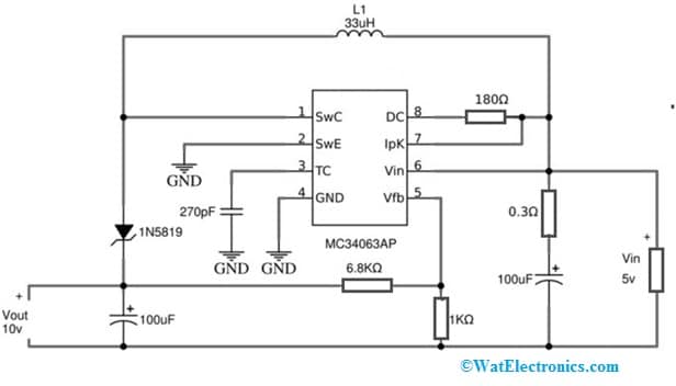
Here we are designing a boost converter circuit with MC34063 IC. So the circuit diagram of the boost converter with MC34063 IC is shown below. Generally, a boost converter is a DC-to-DC converter, used to increase the voltage while reducing the current from its input supply to the load connected at output.
It is a type of SMPS with a minimum of one semiconductor, a diode, and an energy storage element like a capacitor, an inductor (or) the two in combination. Here, the boost converter circuit is designed with MC34063 IC and some external components. So this IC is apt for compact DC-to-DC boost converter circuits which have a primary circuit that is required for designing simple DC-DC converters. This circuit is mainly designed to increase 5V to 10V input voltage with a single source of power supply.
The required components to make this circuit mainly include; MC34063 IC, 1N5819 Schottky diode, 33µH Inductor, two 100µF electrolyte capacitors, 270pF ceramic capacitor, resistors like 0.3Ω, 6.8KΩ, 1KΩ & 180Ω, and 5V power supply. Connect this boost converter circuit as per the diagram shown below.

Boost Converter Circuit with MC34063 IC
Working
The MC34063 IC in the above circuit is connected as a DC-to-DC boost converter. So here, a 5V supply is provided to the circuit as the input voltage which can be increased to 10 Volt. Thus, this circuit can give the required specific output voltage for your requirement with a comparator, internal temperature compensated reference, 100 KHz oscillator, a driver, a PWM controller including active current limiting, and a high current o/p switch. Once this circuit is connected then the output voltage is calculated by using the below formula.
Vout = 1. 25 (1 + (R2/R1))
By changing the R1 and R2 values, the required output voltage can be generated. But the practical op voltage may change slightly because of the inductor value & specification. So, it can be taken as a theoretical o/p voltage & applied bias to the boost converter circuit to check the output voltage & compare them both. Thus, this is how this circuit can be used as a variable o/p DC-DC converter.
Thus, this boost converter circuit is used to bias or drive output actuators within the microcontroller (or) microprocessor-based design.
Advantages and Disadvantages
The advantages of MC34063A IC include the following.
- MC34063A IC is versatile, easy to use, reliable, low cost, etc.
- It offers adjustable output voltage, short circuit current limiting, and a low standby current.
- This IC provides wide input that ranges from 3 Volts to 40 Volts.
- It delivers up to 1.5 Amps of output current.
- This IC can adjust the output voltage.
- This IC has less standby current consumption.
- It has a precision internal reference with a 2% tolerance
- Its oscillator frequency is up to 100 kHz.
The disadvantages of MC34063A IC include the following.
- These buck converter ICs cannot work at high voltages.
- Generally, these circuits are fragile.
- They have a limited power rating.
- They can generate more noise throughout the operation.
Applications
The applications of MC34063 IC include the following.
- MC34063 IC is used in chargers, portable devices, power management, voltage regulator circuits, consumer electronics, communications & networking, and electronic applications with abnormal power needs.
- This IC is used in boost (step-up), buck (Step-down) & voltage-inverting based applications.
- This DC-DC converter IC is used within automobile phone chargers to adjust 5Volts for mobile phones.
- This IC can be utilized in different regulation and power management circuits like inverters, DC-DC converters, charge pumps, and many more.
- The MC34063 IC includes all the main circuitry required for designing simple DC-to-DC converters.
- These DC-to-DC converter ICs are used in electric vehicles, portable devices, military and
- Industrial systems, renewable energy, factory automation, robotics, power electronics, transportation, measuring, and telecommunication equipment.
Please refer to this link for the MC34063 IC Datasheet.
The MC34063 IC is a monolithic DC-to-DC converter IC, available in an 8-pin SOIC or DIP package. This IC includes a low standby current consumption, a wide range of input voltage supply & output voltage regulation. This converter IC is used to design DC/DC converters within boost, buck & reverse voltage polarity topologies. So this IC can be utilized in different power conversion-based applications. Here is a question for you, what is LM2596 IC?