The term ‘monolithic’ in monolithic IC comes from the Greek words like monos & lithos where monos means single and lithos means stone. So the term monolithic involves that the circuit is manufactured in a single crystal. Sometimes, this kind of IC is explained as a planar IC, because it is available in a flat surface form. A monolithic IC is a single silicon piece that includes a whole electronic circuit (or) various circuits. These ICs are the most significant components within modern electronic devices which range from spacecraft to smartphones. The main benefits of these ICs include; being smaller, lighter, more efficient, consuming less power, and reliable. This article provides a basic overview of the LM2577 IC, pinout, features & specifications.
What is LM2577 IC?
The LM2577 is a monolithic regulator IC that is designed to provide power & also control for flyback, step-up & forward converter-based switching regulators. This is a simple-to-use and cost-effective IC because it uses less number of external components. These ICs are available in three output voltage versions adjustable, 12V & 15V. This chip is included with a 3.0Amps NPN switch with associated protection circuitry, thermal limiting & under voltage lockout.
This IC is available in various packages like; 16-Lead DIP, 5-Lead TO-220, TO-263 5-Lead Surface Mount, and 24-Lead Surface Mount. The significant features of this regulator IC include; a fixed 52 kHz frequency oscillator, a soft start mode to decrease in-rush current throughout start-up & current mode control for better input voltage rejection & output load transients.
LM2577 IC Working
LM2577 3A regulator IC step-ups the input voltage from 3Volts to 34Volts to high output voltage from 3.5Volts to 40Volts at 3A continuous current based on the I/O voltage settings. This is a boost converter IC where the output voltage will be high as compared to the input voltage. Thus, it provides excellent line and load regulation because it drives a 3Amps load current. Whenever the output current exceeds 2Amps, a heat sink is used to keep away from thermal damages.
This is a low-cost step-up power module booster with current limiting and over-current features. So, 3Amps in-built efficient MOSFET switch attains up to 92% efficiency by providing better results & a less ripple factor. This IC uses small-capacity filter components as compared to the low-frequency-based switching regulators. So this regulator reduces the overall size of the board to save its space.
LM2577 IC Pin Configuration:
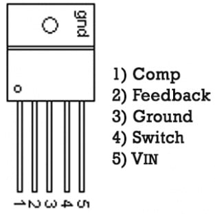
LM2577 IC pin configuration is shown below. This IC includes 5-pins which are discussed below.

LM2577 IC Pin Configuration
- Pin-1 (COMP): It is a compensation pin of the voltage regulator IC. This is the output of the in-built error amplifier. So the compensation network is located at this pin within power supplies through outside compensation networks.
- Pin-2 (FB): It is a feedback pin that allows the voltage regulator to adjust & measure the o/p voltage. So this can be done with a feedback loop that assists the voltage regulator to respond to changes within input voltage, power rail transients, and load.
- Pin-3 (GND): It is a ground pin of the voltage regulator IC that connects to the common GND of the circuit. So this pin provides a steady reference potential & performs as a reference point mainly for the operation of the regulator.
- Pin-4 (SW): It is a switch pin of the voltage regulator IC.
- Pin-5 (Vin): It is an input pin of the IC.
LM2577 IC Features and Specifications:
The features and specifications of LM2577 IC include the following.
- LM2577 is a step-up converter voltage regulator IC with a heat sink
- This IC includes 5 pins.
- Its size is compact.
- Its input voltage ranges from 3.5V to 40V.
- It has a 52 kHz internal oscillator.
- Output current is up to 2Amps.
- Output voltage ranges from 5 to 56V.
- Its conversion efficiency is up to 92%.
- Load regulation and voltage regulation are ± 0.5%.
- Its length x width x height in mm is 52 x 22 x 20.
- Its weight is 13 grams.
- Its soft-start function decreases in-rush current during start-up.
- The sheath type is TO-220-5.
- Its mounting type is BOTTOM.
- Its operating temperature ranges from -40 to +85 C.
Equivalents and Alternative ICs
Equivalent LM2577 ICs are; LM2577T-12/LF03, LM2577T-12, LM2577T-12FLOWLB03 and LM2577T-12/LB03. An alternative to LM2577 IC is LM1577.
Step-up Switching Regulator Circuit with LM2577 IC
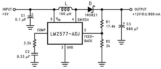
The step-up switching regulator circuit with LM2577 IC is shown below. This circuit steps up the voltage from 5V to 12V with 800mAmps of a max output current. This circuit is very simple to design and cost-effective.
The required components to make this circuit mainly include; LM2577 IC, typical 100µH inductance, 1N5821 Schottky Barrier Rectifier diode, 0.1µF low ESR capacitor, 0.33µF capacitor, 680µF/25V low ESR electrolytic capacitor, 17.4k and 2K resistors. Connect this circuit as per the diagram shown below.

Step-up Switching Regulator Circuit with LM2577 IC
Working
The step-up switching regulator circuit uses LM2577 adjustable voltage regulator IC, however, the 12Volts LM2577T-12 fixed-voltage version can also work if you take away both the R1 and R2 resistors and connect the feedback pin to the output of the regulator directly. By choosing different R1 & R2 values, you can utilize the LM2577-ADJ or LM1577-ADJ to generate different voltages. So output voltage can be given by the formula like; VOUT = 1.23V (1 + R1/R2).
The C1 input capacitor in the circuit must be a low ESR, good quality & 0.1 µF capacitor with the cut leads as small as possible. If this IC is arranged far from the source of filter capacitors supply then 10µF to 100µF additional larger electrolytic capacitor is necessary.
Here, a low ESR type capacitor is selected for the C3 output filter with at least 20% higher working voltage as compared to the output voltage so, low ESR values can be attained with larger capacitor values (or) by paralleling several smaller-value capacitors.
Small Solar Plant with LM2577 IC
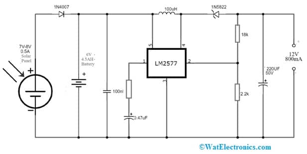
The solar plant circuit with LM2577 voltage regulator IC is shown below. This circuit is designed to change the photonic sunlight energy into electricity indirectly either using CSP (concentrated solar power) or directly with PV (Photovoltaics). This solar power system uses mirrors or lenses to focus a large sunlight area into a little beam. So these are important and fairly cheap electrical energy sources which can be used wherever grid power is not convenient, costly to connect (or) simply unavailable.
The required components to make this circuit mainly include; a breadboard, 9V battery, 7V to 8V, 0.5A, 4W solar panel, LM2577 voltage regulator IC, 1N5822 Schottky diode, 1N4007 diode, Heat sink, 100uH Inductor, 220uF/50V, 0.47uF polar capacitors, 100nF non-polar capacitor, 18K and 2.2K resistors.

Small Solar Plant with LM2577 IC
Working
The LM2577 is a monolithic chip that supplies all the power & control functions for flyback, boost & forward converter switching regulators. This chip is available in different output voltage versions like; 12Volts, 15Volts & adjustable.
These regulators are simple to use and cost-effective and use fewer external components. The main features of this IC include a 52 kHz fixed-frequency oscillator, a soft start mode to decrease in-rush current in start-up & current mode control for better input voltage & output load transient rejection.
The solar cell in the above circuit charges the 6Volts SLA battery in the morning. Whenever the battery gets charged then it provides 6Volts to the voltage booster circuit which is built in the region of an LM2577 IC. This circuit boosts voltage from 6 volts to 12 volts with 0.8Amps current.
The battery on a full charge shows 7.2Volts with the connected solar panel and whenever it is not charging (or) the solar panel is not coupled then its voltage will drop for a few hours from 6.3Volts to 6.4Volts. Thus, this circuit is used in DIY home projects to run tiny devices like; light fixtures, PCs, fans, etc.
Advantages & Disadvantages
The advantages of LM2577 IC include the following.
- LM2577 IC provides outstanding line & load regulation because it drives a 3A of load current.
- It generates single (or) various output voltages that are greater or lower as compared to the input supply voltage.
- These monolithic ICs provide all of the power & control functions to step up.
- It is available in three different o/p voltage versions.
- This IC needs fewer external components.
The disadvantages of LM2577 IC include the following.
- The main disadvantage of the LM2577 IC is that its o/p current cannot be limited internally whenever
- utilized as a step-up regulator. So, the current should be limited externally to 6.0Amps to avoid harm to the switch.
- It is an older product with a large footprint.
Applications
The applications of LM2577 IC include the following.
- The LM2577 monolithic IC provides all of the control functions and power for forward, boost and flyback converter switching regulators.
- \This switching regulator produces an output voltage higher than the input voltage supply.
- This boost converter IC provides outstanding line & load regulation because it drives 3Amps of load current.
- This regulator is mainly designed for high-power LED driving and lithium-ion battery charging applications because it maintains a stable output even with quite variable input.
- This DC-to-DC step-up power converter is ideal for battery-operated projects that need a regulated power supply.
Please refer to this link for the LM2577 IC Datasheet.
Thus, this is an overview of LM2577 IC, pinout, features, specifications, and applications. This is a monolithic IC, available in different output voltage versions like; 12V, 15V & adjustable. Its operating voltage ranges from 3.5Volts to 40Volts and it has a soft start mode, current mode control, and 52 kHz fixed-frequency oscillator. This IC can also have a 3.0Amps NPN switch including protection circuitry for current limiting, under voltage lockout, and thermal limiting. This is a cost-effective IC that needs less number of external components. The current to this IC must be limited externally to 6.0Amps to avoid harm to the switch. Here is a question for you, what is LM1577 IC?