An electric motor is a more frequently used actuator in any machine or electronic device which is used from a vibration motor within mobiles to stepper motors within CNC machines. These motors’ motion & direction can be controlled through a motor controller or motor driver using a processor or microcontroller. The motor driver output is in digital form thus it uses pulse width modulation for controlling the motor. There are different types of motor driver ICs available in different sizes and shapes but the most frequently used ones are ULN2003 and L293DIC. This article discusses an overview of the L293D motor driver IC, its working, and its applications.
What is L293D Motor Driver IC?
L293D is a 16-pin motor Driver IC used to drive two electrical motors simultaneously. This IC allows us to drive a motor in any direction & also controls the motor speed. This IC provides up to 600 mA of bidirectional drive currents from 4.5 to 36 voltages. Motor driver ICs can also drive different inductive loads like solenoids, bipolar stepping motors, relays, transformers, and high-voltage or high-current loads within positive-supply applications.
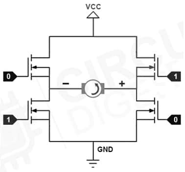
This L293D motor driver IC works on the basic H-bridge principle to control the DC motor’s rotation direction. In this principle, the H-Bridge controls the rotating direction of the DC motor by simply changing its input voltage polarity. An H-bridge circuit generally has four transistors like BJTs or MOSFETs and the motor in the middle forms an H-bridge configuration. The current flow direction can be changed by simply triggering two particular switches simultaneously, so in this way, the motor’s rotation direction in any direction can be changed.
Pin Configuration:
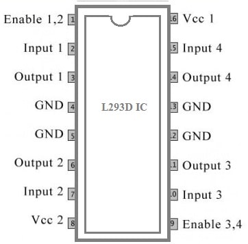
The pin configuration of L293D IC is shown below. This IC includes 16 pins which include 4 GND pins, 4- i/p pins, 4-o/p pins, 2-enable pins, and 2-voltage pins which are discussed below.

L293D IC Pin Configuration
Pin1 (Enable1,2): Once this Enable1,2 pin is logic high, then the left side of this will work and when this pin is logic low, the left side of the IC doesn’t work. Thus, for the left side of the motor driver IC, this is the Master Control pin.
Pin2 (Input -1): Once this input1 pin is high then output-1 will become High thus the flow of current will be throughput output-1
Pin-3 (Output-1): This output-1pin is directly connected to one of the motor-1 terminals.
Pin-4 & 5 (Ground): These are GND pins that are connected to the ground terminal of the circuit.
Pin-6 (Output-2): This o/p-2pin is directly connected to motor-1’s one of the terminals.
Pin-7 (Input-2): Once this i/p-2 pin is logic high, then output-2 will become high, thus the current supplies throughout output-2.
Pin-8 (VCC-2): This VCC-2 pin is used to provide the required voltage to make the motor run. This voltage can be greater as compared to the Vcc-1 voltage of IC.
Pin-9 (Enable-3,4): Once this pin is high, the right side of the driver IC will properly work. Similarly, when this pin is low the right side of the IC doesn’t work. Thus, for the right side of the IC, this is the Master Control pin.
Pin-10 (Input-3): When this Input-3 pin is high then output3 will become high thus the current will flow throughout output3.
Pin-11 (Output-3): This o/p-3 pin is connected directly to one of the motor-2 terminals.
Pin-12 & 13 (GND): These GND pins must be connected to the ground terminal of the circuit.
Pin-14 (Output-4): This o/p-4pin is connected directly to one of the motor-2 terminals.
Pin-15 (Input-4): When this Input-4 is High then o/p-4 will become High, thus current flows throughout o/p-4
Pin-16 (VCC-1): This VCC1 pin simply supplies power to the driver IC. Thus, this pin must be supplied by 5V.
Features & Specifications:
The features and specifications of L293D IC include the following.
- This motor driver IC is available in different packages like 16-pin DIP, SOIC & TSSOP.
- This motor driver is capable of running Two DC motors.
- By using this IC, controlling motor speed & direction is possible.
- The Vcc2 voltage ranges from 4.5V – 36V.
- The maximum Peak current of the motor is 1.2Aps.
- The maximum continuous current of the motor is 600mAmps.
- The Vcc1 voltage supply ranges from 4.5V – 7V.
- Its transition time is 300ns at 5V & 24V.
- It has automatic thermal shutdown.
- It has ESD protection internally.
- It has high noise immunity inputs.
- The output current of this IC is 1 amps for each channel.
- Its peak o/p current is 2 amps for each channel.
- The operating temperature of this IC is ranges from 0°C – 70°C.
- The equivalent L293D ICs are; ULN2003, SN754410 & LB1909MC and alternative L293D IC is TB6612FNG.
DC Motor Controlling using a Microcontroller
The speed and direction of the DC motor can be controlled using two techniques; PWM and H-bridge. The PWM technique is used for controlling the motor speed whereas the H-bridge is used to control the direction of motor rotation.
PWM
To change the DC motor speed, the amplitude of the applied input voltage to the DC motor needs to be changed. For that, the PWM technique is used, so in this technique, the voltage applied to the motor can be changed by transmitting a sequence of pulses thus the output voltage is proportional to the generated pulse width by the microcontroller which is called duty cycle. When the duty cycle is higher, then the average voltage that is provided to the motor is higher. Similarly, when the duty cycle is shorter, the average voltage provided to the motor will be lower.
H-Bridge
To change the rotation direction of a motor, you have to change the voltage supply polarity. For that, an H-Bridge motor driver is used. This H-bridge motor driver includes four MOSFETs and the DC motor is arranged in the middle of the circuit to form the H-bridge structure. By enabling or disabling two opposite switches, the direction of the current flow can be changed so that the rotation direction of the DC motor can be changed.

H-Bridge Circuit
L293D Motor Driver IC Interfacing to an Arduino
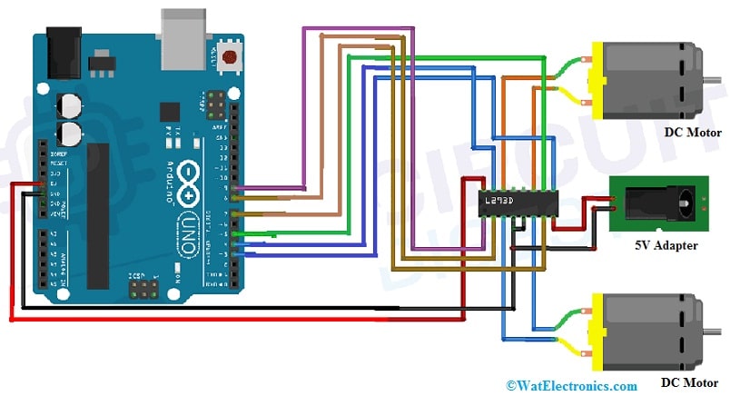
The L293D motor driver IC interfacing with Arduino is shown below. This interfacing can be used to rotate the DC motor direction & control the motor speed. The required components to make this connection mainly include an Arduino Uno board, L293D motor driver IC, DC motors, connecting wires, and a 5V adapter.
The connections of L293D motor driver IC interfacing to an Arduino follow as;

L293D Motor Driver IC Interfacing to an Arduino
- In this interfacing, a 3V small DC gear motor is used and the motor driver IC is powered with an external 5V power supply to the motor driver IC’s VCC1 pin.
- Connect 5V to the IC’s VCC2 pin which provides supply to the inside logic circuit of the L293D IC.
- The pins 3 & 9 of the L293D IC are connected to Arduino’s ENA & ENB pins. Here, both pins 3 & 9 are PWM pins thus we can control the motor speed through an Arduino board.
- The pins 4,5, 7 & 8 of L293D IC are simply connected to the Arduino’s IN1 to IN4 pins.
- The output pins like OUT1 to OUT4 of IC are connected to the DC motor like OUT1 and OUT2 to one motor and OUT3 & OUT4 to another motor.
Code
The required code for interfacing the L293D motor driver IC with an Arduino is shown below.
// L293D Motor Driver IC Interfacing to Arduino
// Define motor control pins
const int motorPin1 = 2; // Input 1
const int motorPin2 = 3; // Input 2
const int enablePin = 9; // Enable pin (PWM)
void setup() {
// Set motor control pins as output
pinMode(motorPin1, OUTPUT);
pinMode(motorPin2, OUTPUT);
pinMode(enablePin, OUTPUT);
}
void loop() {
// Move the motor forward
moveMotorForward();
delay(2000); // Wait for 2 seconds
// Move the motor backward
moveMotorBackward();
delay(2000); // Wait for 2 seconds
// Stop the motor
stopMotor();
delay(1000); // Wait for 1 second
}
void moveMotorForward() {
// Set motor direction
digitalWrite(motorPin1, HIGH);
digitalWrite(motorPin2, LOW);
// Set motor speed (0 to 255)
analogWrite(enablePin, 150); // Adjust the speed as needed
}
void moveMotorBackward() {
// Set motor direction
digitalWrite(motorPin1, LOW);
digitalWrite(motorPin2, HIGH);
// Set motor speed (0 to 255)
analogWrite(enablePin, 150); // Adjust the speed as needed
}
void stopMotor() {
// Stop the motor by disabling the PWM
analogWrite(enablePin, 0);
}
In the above example:
- motorPin1 and motorPin2 are the input pins for controlling the motor direction.
- enablePin is the PWM pin for controlling the motor speed.
- The moveMotorForward, moveMotorBackward, and stopMotor functions are used to control the direction and speed of the motor.
Make sure to connect the corresponding pins from the Arduino to the L293D as per your wiring. Adjust the pin numbers and motor speed values according to your specific setup.
Before connecting a motor driver to a microcontroller certain points need to be considered. Please click on this link to know more about Connecting a Motor Driver to a Microcontroller.
The L293D motor driver interface with various microcontrollers:
It is not limited to Arduino. Here are some examples of other popular microcontrollers:
- Raspberry Pi: The Raspberry Pi can be used to control motors using the L293D. GPIO pins on the Raspberry Pi can be configured for motor control.
- PIC Microcontrollers: Microcontrollers from Microchip’s PIC family, such as PIC16 or PIC18, can be used with the L293D for motor control applications.
- STM32 Microcontrollers: STM32 microcontrollers from STMicroelectronics provide a wide range of options for motor control, and they can be used with the L293D.
- ESP8266 and ESP32: These Wi-Fi-enabled microcontrollers from Espressif can also be used for motor control using the L293D, and they offer the added advantage of wireless control.
- ATmega series (e.g., ATmega328): Apart from Arduino, other microcontrollers from the ATmega series can be interfaced with the L293D.
- BeagleBone Black: BeagleBone Black is another single-board computer that can be used for motor control applications.
- ARM Cortex-M Microcontrollers: Various microcontrollers based on ARM Cortex-M architecture, such as those from NXP, STM32, and others, can be interfaced with the L293D for motor control.
When interfacing the L293D with different microcontrollers, make sure to consider the voltage and current requirements of your motors and the compatibility of the microcontroller’s output signals with the L293D inputs. Always refer to the datasheets of the components and microcontrollers for accurate information on pin configurations and electrical characteristics.
Advantages & Disadvantages
The advantages of L293D IC include the following.
- These motor Driver ICs are very famous and not expensive as compared to other motor driver ICs.
- These are the most frequently used ICs because of simple control, and the right size; it doesn’t require protective circuit & diodes, high-speed deviations, excellent resistance to temperature & doesn’t require heat sinks.
- L293D IC permits the DC motor to drive in two directions.
- This IC controls a set of two motors instantaneously within any direction.
- Motor driver ICs can also perform as current amplifiers because they use a low-current control signal & provide a higher-current signal to drive the DC motors.
- It is very easy to connect versatile & widely used motor driver IC.
- This module fits within Arduino MEGA and UNO R3 Board.
The disadvantages of L293D IC include the following.
- The L293D motor driver will not work if the voltage is less than 4.5V and the voltage is above 36V then it will harm the device.
- While working with motor driver IC, the winding resistance of the motor needs to be considered because if the winding resistance of the DC motor is low then it consumes more current as compared to its rated current & that can harm the device.
L293D Motor Driver IC Applications
The applications of L293D IC include the following.
- L293D motor Driver IC is used to drive two DC motors and control direction & speed simultaneously in any direction.
- These ICs are normally used in autonomous systems.
- These ICs are used to drive high-current electric motors with digital circuits.
- These ICs also drive stepper motors.
- Its common applications mainly include stepping motor drivers, DC motor drivers, relay drivers, etc
- These ICs are frequently used in robotic applications by allowing DC motors to run backward or forward.
- This IC can be used in street racing cars, small cars for children, and robots because of a separate supply for the DC motor.
Please refer to this link for the L293D Motor Driver IC Datasheet.
Thus, this is an overview of the L293D motor driver IC, pin configuration, features, specifications, circuit, and its applications. The L293D IC is mainly designed for providing upto 600-mA of bidirectional drive currents at 4.5 V to 36 V. Here is a question for you, What is ULN2003 motor driver IC?