An encoder is one type of detecting device that is used to change motion into an electrical signal and this signal can be read with a control device within a motion control system like PLC. This encoder transmits a feedback signal to determine speed, position, direction, and count. There are different types of encoders available like optical, magnetism, linear, quadrature, magnetical, incremental rotary, rotary, encoder absolute, and incremental. So this article discusses one of the types of encoders like the KY-040 rotary encoder, working and its applications.
What is KY-040 Rotary Encoder?
A KY-04 rotary encoder is a type of encoder that looks similar to a potentiometer; however, it generates a set of pulses. Once this encoder’s knob is rotated in the clockwise (or) anti-clockwise direction, it turns in small steps and generates digital or analog signals which are useful in controlling servo motors, stepper motors, measuring the lengths, brightening & dimming of lights, increasing or decreasing digital values, etc.
Pin Configuration:
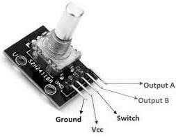
The pin configuration of the KY-040 rotary encoder is shown below. This encoder includes five pins which are discussed below.

KY-040 Rotary Encoder Pin Configuration
- Pin 1 (GND): It is a GND connection pin.
- Pin 2 (VCC): It is an input voltage pin of the sensor, so it can be connected to 3.3V/5V.
- Pin 3 (SW): It is the o/p of the push button switch. Once the knob of this encoder is depressed, then the voltage will go LOW.
- Pin 4 (DT): It is a second output pin used to determine the position of the encoder.
- Pin 5 (CLK): It is the first output pin used to determine the rotation of the encoder.
Features & Specifications:
The features & specifications of the KY-040 rotary encoder include the following.
- The KY-040 is a rotary i/p device and it provides a sign of how much the encoder’s knob has been turned & in which way it is turning.
- This module has an integral push button switch that is used to change the function of the switch like switching between coarse & fine adjustments.
- Its operating voltage is 5V DC
- The resolution rotary encoder is 20 pulses for each rotation.
- Its operating temperature ranges from -20℃ to +70℃.
- The dimension of the rotary encoder is 30mm x 18mm x 30mm.
- Its mechanical angle is 360 degrees.
- Its output is two-bit gray code.
- Alternatives KY-040 rotary encoders are; PEL12S-2024S and M274.
- This encoder is compatible with different controller boards like Raspberry Pi, Arduino, etc.
KY-040 Rotary Encoder Working
A KY-040 rotary encoder includes a slotted disc including conductive pads located at an equivalent distance above this disc. This disc includes two output pins A & B which are connected on top of the disc. So whenever the knob is turned then the two conductive pads will get in touch with the two o/p pins. Here, the circular disc is connected to a common GND or pin C.
Once you rotate the knob, then two output pins will make contact with pin C in a particular order based on which way you revolve the knob. So when they make contact, two signals will be generated which are out of phase with 90°.
Whenever the knob is rotated in a clockwise direction, then pin-A connects to GND before the output pin-B. Similarly, when the knob is rotated in an anticlockwise direction, then pin-B connects to GND before the output pin-A. By checking when every pin connects/disconnects from GND, then we can decide the direction of knob rotation. So this can be achieved by observing the condition of B when the condition of A changes.
The output pins A & B generates output waveform which is shown in the above diagram respectively. Here two pulses are required to identify the knob in which way it has been turned. In the above diagram, if you observe two pulses, they are 90 degrees out of phase. Thus whenever the knob is turned in clockwise then first Output-A goes high & the knob is turned in anti-clockwise then first Output-B goes high.
KY-040 Rotary Encoder Interfacing with Arduino Uno
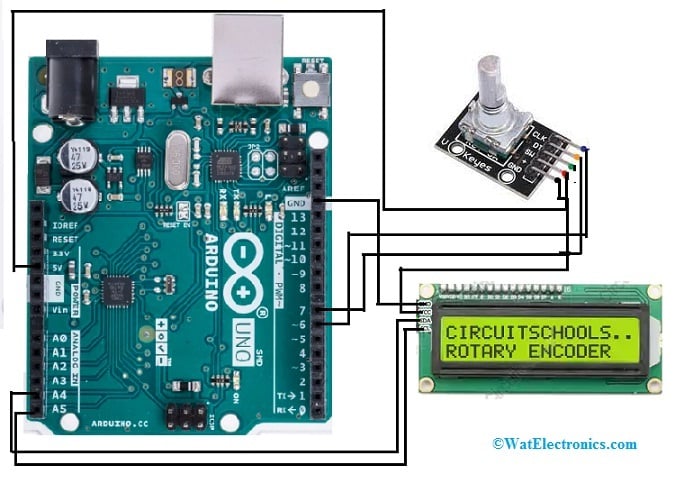
The KY-040 rotary encoder interfacing with Arduino Uno is shown below. This interfacing displays the encoded directional values using a 16X2 LCD display once turned in both clockwise and anti-clockwise directions. The required components to make this interfacing mainly include a KY-040 rotary encoder, Arduino Uno, 16X2 LCD display with I2C adapter, and connecting wires.
The connections of the rotary encoder to Arduino Uno follow as;
- The VCC pin of the KY-040 rotary encoder is connected to the 5V pin of an Arduino Uno and the VCC pin of the LCD.
- The GND pin of KY-040 is connected to the GND pin of an Arduino Uno & GND pin of the LCD.
- The output pins of encoders like CLK & DT are simply connected to Arduino’s digital pins like pin-6 & pin-7 respectively.
- The I2C communication pin of LCD-like SDA is connected to the A4 pin of the Arduino board.
- The I2C communication pin of LCD-like SCL is connected to the A5 pin of the Arduino board respectively.

KY-040 Rotary Encoder Interfacing with Arduino Uno
Code
// Define the pins for the rotary encoder
#define ENCODER_DT_PIN 2
#define ENCODER_CLK_PIN 3
#define ENCODER_SW_PIN 4
// Variables to store the state of the encoder
volatile int encoderPos = 0;
volatile boolean rotating = false;
volatile boolean buttonPressed = false;
// Interrupt service routine for handling rotary encoder rotation
void handleEncoder() {
rotating = true;
if (digitalRead(ENCODER_DT_PIN) == digitalRead(ENCODER_CLK_PIN)) {
encoderPos++;
} else {
encoderPos–;
}
}
// Interrupt service routine for handling rotary encoder button press
void handleButton() {
buttonPressed = true;
}
void setup() {
// Initialize serial communication
Serial.begin(9600);
// Set pins as inputs
pinMode(ENCODER_DT_PIN, INPUT_PULLUP);
pinMode(ENCODER_CLK_PIN, INPUT_PULLUP);
pinMode(ENCODER_SW_PIN, INPUT_PULLUP);
// Attach interrupt for rotary encoder rotation
attachInterrupt(digitalPinToInterrupt(ENCODER_DT_PIN), handleEncoder, CHANGE);
// Attach interrupt for rotary encoder button press
attachInterrupt(digitalPinToInterrupt(ENCODER_SW_PIN), handleButton, FALLING);
}
void loop() {
// Check if the encoder is rotating
if (rotating) {
Serial.print(“Encoder Position: “);
Serial.println(encoderPos);
rotating = false;
}
// Check if the encoder button is pressed
if (buttonPressed) {
Serial.println(“Button Pressed!”);
buttonPressed = false;
}
// Add any additional code here as needed
// This loop runs continuously
}
Once the interfacing connections are made, then upload the following code and connect the Arduino Uno board to a PC wherever Arduino IDE is installed. Select the type of Arduino board as well as the proper port using the Tools menu. Now, need to install the necessary libraries (LiquidCrystal_I2C) from the in-built Library manager otherwise you can easily download the most recent version from the Github site. Now copy and paste the following code within IDE & push the upload button.
Once the above code is uploaded then open the serial monitor at a 9600 baud rate & make sure the knob position & the rotation direction are. Thus when you turn the knob in anti-clockwise, then the counter position will increase & also reduces whenever you turn the knob anti-clockwise. Finally, the position and direction of the encoder will be displayed on the LCD.
In the above code the loop() function constantly checks the rotating and buttonPressed flags. When rotating is true, it updates the LCD with the current encoder position. When buttonPressed is true, it displays a “Button Pressed!” message on the LCD. Before displaying new information, it clears the previous message by writing spaces.
This code demonstrates basic input reading (from the rotary encoder) and output display (on the LCD) with an Arduino, using interrupts for efficient background input handling.
Advantages
The advantages of the KY-040 rotary encoder include the following.
- This encoder module has 360 degrees of free rotation.
- This encoder is incremental type.
- It provides 20 cycles for each revolution.
- It works with low voltages.
- This module is very simple to interface with any controller.
- It has a long life.
- The knob of this encoder helps in controlling different motors through precision.
Applications
The applications of the KY-040 rotary encoder include the following.
- KY-040 rotary encoder is suitable in the applications of volume knob & changing lighting voltage.
- The rotary encoder module is used in prototyping applications like multimedia speakers, smart homes, automotive electronics, instrumentation, digital potentiometers, etc.
- This encoder provides an indication regarding the rotation of the knob & its direction.
- This module can also be used for controlling digital potentiometers.
- These encoders include a knob to control different motors with accuracy like a servo or stepper.
- This encoder is a very inexpensive module, so used to create potentiometers otherwise to implement a simple to utilize human interface.
- This module is used in different rotation encoding functions like DSO controls, shaft rotation positioning, instruments control digitally, power supplies controlled digitally, etc.
- It is used in the arm controller of robotics.
- It is used to control motor movement precisely.
Please refer to this link for KY-040 rotary encoder datasheet.
Thus, this is an overview of a KY-040 rotary encoder, specifications, interfacing, and its applications. This type of encoder is used for measuring the rotary motion of devices or machines. This encoder includes a push switch that helps in extending the encoder module functionality. Here is a question for you, what is an encoder?