The first ‘Joystick technology’ was introduced in the early 20th century for use in aircraft. So this was patented by Ralph Baer in 1944 who invented the first video game console. So joysticks were used widely in video games in the years 1970s & 1980s. Joysticks are used as controlled devices in elevators & aircraft ailerons. So these are first used on the Bleriot VIII aircraft of Louis Bleriot in combination with a foot-controlled rudder bar on the tail for the yaw control surface. This article elaborates on the KY-023 joystick module, its workings, and its applications.
What KY-023 Joystick Module?
Joystick Module is an input device, used to measure movement within two X and Y directions in gaming, remote control, robotics, etc. So this module controls the movement of the pointer within a dimension axis. The Joystick module includes two potentiometers for reading the operator’s input which are connected between +VCC & GND. So they simply perform as voltage divider networks.
In this module, one potentiometer is utilized to obtain the analog output voltage for X-direction movement whereas the other one is for Y-direction movement. These modules’ construction is very simple and low cost but pretty helpful in various applications like general experimenting & incorporating into a last application for robotic control. The joystick includes one freewheeling holder, so based on the holder movement the knob of the potentiometer will be changed its position & resistance.
How KY-023 Joystick Module Work?
The Joystick module works on the resistance change principle of two 10-kilo ohms potentiometers whenever the joystick is shifted. So this resistance will be changed into voltage, and after that, it will be interpreted as movement through a computer program.
The joystick module includes two potentiometers which are placed at a 90-degree angle. So these are arranged to a small stick centered through springs. Whenever the joystick is within a resting position, the output will be approximately 2.5 volts. Once the joystick is turned, the output changes from 0Volts to 5Volts based on its direction. These modules can be utilized to control a variety of things like cameras, games, robots, etc.
Pin Configuration:
The KY-023 Joystick module pin configuration is shown below. This module includes five pins which are explained below.
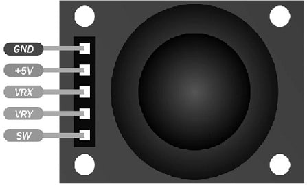
Joystick Module Pin Configuration
- Pin – 1 (VCC): It is a voltage supply pin of the module which provides a +5V supply to the module.
- Pin-2 (X-OUT): This pin supplies an analog output voltage that ranges from 0V to VCC based on the Holder movement within the X-axis.
- Pin-3 (Y-OUT): This pin provides an analog o/p voltage from 0V to VCC based on the Holder’s movement within the Y-axis.
- Pin-4 (Switch): This is a tactile switch. Whenever this switch is pushed, then this pin is connected to GND. Similarly, when this switch is not pushed, then this pin will be connected to VCC throughout a resistor.
- Pin-5 (GND): It is a ground pin of the module which is connected to the negative terminal of the power supply.
Features & Specifications:
The features and specifications of the Joystick module include the following.
- Its operating voltage ranges from 3V to 5V DC.
- The output is in the analog voltage form.
- This module includes two potentiometers for the X & Y axis which measures the position.
- Its operating temperature ranges from 0 to 70 °C.
- It auto-returns to middle position
- These modules have cup-type knobs and are less weight.
- It is compatible with different microcontrollers.
- Dimensions are 1.57 x 1.02 x 1.26 inches.
Equivalents & Alternatives
Equivalent KY-023 joystick modules are; the Teyleten Robot Dual-axis XY joystick module & the PS2 game joystick control stick sensor. Alternatives to KY-023 joystick modules are; dual-axis XY joystick module and Arduino joystick library 2.0.
Joystick Module Components
The Joystick module is a PlayStation-2 (PS2) controller which is a self-centering spring-loaded joystick that means it will go center itself whenever you release it. It can also have a comfortable cup-type cap or knob that looks like a thumbstick. Joystick module components mainly include; potentiometers, pushbutton switches, and caps which are explained below.
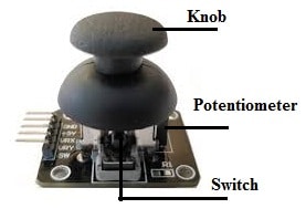
Joystick Module Components
Potentiometers
The fundamental design behind a joystick is to change the position of a stick on two axes like the X-axis from left to right & the Y-axis (up & down) into an electrical signal. So this signal can be processed by a microcontroller. This can be accomplished by connecting two 5K potentiometers with a gimbal mechanism that separates vertical & horizontal movements.
The potentiometers of the joystick module are two gray boxes arranged on any side of the module. Whenever the joystick is moved by keeping a look at the potentiometer, then each potentiometer will detect movement in a single direction only.
Pushbutton Switch
This joystick module contains a momentary pushbutton switch that is activated whenever you push the joystick knob. Once the knob is pushed down then a lever will be pushed down on the head of a switch. So it is designed in such a manner that the lever works regardless of the location of the joystick.
Knob or Cap
The joystick module includes a black color knob or cap which helps to shift the potentiometer & provide a level controlling experience. In addition, it can also be used to function the switch by pushing down the knob.
2-Axis Joystick Module Circuit
The joystick module circuit generally includes one Switch and two potentiometers like VR1 & VR2. In the below circuit diagram, the VR1 potentiometer represents X-axis whereas the VR2 potentiometer represents Y-axis. This potentiometer has a knob, whenever it rotates then the output voltage will be changed at the signal pin. So the joystick module knob can be connected to VR1 & VR1 potentiometers knobs.
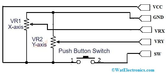
KY-023 Joystick Module Circuit
Whenever we moved the joystick module knob then the potentiometer knob can also be moved, thus the output value of the potentiometer can also be changed. In this way, we can obtain the dissimilar analog output values through the VRx & VRy pins of the module. This module gives analog output from 0V to 5V range.
Now connect the 5-volt power supply to the module. Whenever the module knob is there at the middle position, then it outputs from VRx and VRy pins which are half of the VCC like 2.5V. If the joystick knob is shifted to the +X-axis end then the outputs of VRx and VRy pins will be 5v and 2.5v. If the joystick knob is shifted to the -X-axis end then the outputs of VRx and VRy pins will be 0V & 2.5v.
Similarly, if the joystick knob is shifted to the +Y-axis end then the output of the VRy pin will be 5V & the output of the VRx pin will be 2.5V. If the joystick knob is shifted to the -Y-axis end then the output of the VRy pin will be 0v & the output of the VRx pin will be 2.5v. Generally, the output of the SW pin is low. Once we push the Knob, the output of the SW pin will be high.
Types of Joystick Module
Joystick modules are available in different types like industrial, thumb, finger, and hand grip which are explained below.
Industrial Joysticks
Industrial joysticks are used in cranes, agricultural machinery, oil rigs, excavators, forklifts, and military equipment to position, steer and control. These joysticks have some features like mounting styles, actuator options & controller specifications which include spring return, number of axes, support different protocols, friction hold, etc. These joysticks are robust and can resist harsher environments.
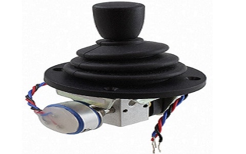
Industrial Joysticks
Thumb Joysticks
Thumb joysticks low-profile type joysticks that provide exact control with different mounting & actuator options to use easily. These joysticks are used in different applications like target acquisition, cursor control, security cameras, automated surgical equipment, robotics, etc.
This is a grove-compatible module, related to the ‘analog’ joystick on PlayStation-2 or PS2 controllers. This joystick has X & Y potentiometers that control 2D movement by providing analog signals. These can also have a push button, used mainly for special applications. Whenever this module is in enable mode, then it outputs two analog values which represent two directions. As compared to other types, its output values can be limited to 200 to 800 ranges.
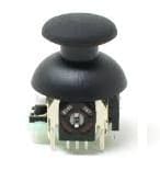
Thumb Type
Finger Joysticks
Finger joysticks are control devices that use a small lever that can be moved in different ways. These are utilized to enter commands on different devices like robots, medical devices, vehicles, etc. These joysticks are used mainly to provide movement & speed control within low-profile units like robotic operations, medical instruments, wheelchairs & applications wherever compact size and precisions are required.
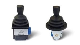
Finger Types
Hand Grip Joysticks
Hand-grip joysticks are heavy-duty joysticks used widely in heavy-duty applications to control vehicles and machinery like forklift vehicles, mobile cranes, robotic machines, agricultural equipment, construction machinery, etc. These joysticks are extremely versatile devices used in several applications like automation systems, remotely operated equipment, etc.
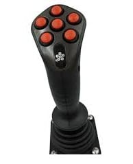
Hand Grip Type
KY-023 Joystick Module Interfacing with Arduino Board
A Joystick module is a device that allows operators to shift a machine within two dimensions forward, backward, right, and left. Thus the main function of a joystick is to provide a microcontroller through an electrical signal equivalent to the location of the stick along with two axes the X-axis, and the Y-axis, left to right & up and down.
The required components to make this interfacing mainly include Arduino UNO, KY-023 2-axis joystick, breadboard, and jumper wires. So the connections of this interfacing follow as;
- Connect the GND pin of Arduino to the GND pin of the 2-axis Joystick.
- Connect the 5V pin of Arduino to the VCC pin of the 2-axis Joystick.
- Connect the A0 pin of Arduino to the VRX pin of the 2-axis Joystick.
- Connect the A1 pin of Arduino to the VRY pin of the 2-axis Joystick.
- Connect the D8 pin of Arduino to the SW pin of the 2-axis Joystick.
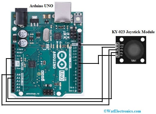
Joystick Module Interfacing with Arduino Board
Code
The required code for this interfacing includes the following.
// Arduino pin numbers
const int SW_pin = 8; X_pin = 0; Y_pin = 1; // digital pin connected to switch output
// analog pin connected to X output
// analog pin connected to Y output
void setup() {
pinMode(SW_pin, INPUT);
digitalWrite(SW_pin, HIGH);
Serial.begin(9600);
}
void loop() {
Serial.print(“Switch: “);
Serial.print(digitalRead(SW_pin));
Serial.print(” | “);
Serial.print(“X-axis: “);
Serial.print(analogRead(X_pin));
Serial.print(” | “);
Serial.print(“Y-axis: “);
Serial.print(analogRead(Y_pin));
Serial.println(” | “);
delay(200);
}
Working
This interfacing can be understood by understanding the above code. So in this code, first we need to define the module’s pins which are connected to the Arduino board. In the above interfacing, we can notice that Adriano’s three pins are used analog & digital to attach the sensor. Thus name those pins to define them like constant integers to keep their values.
After that, the SW pin of the joystick module is declared as input since it uses values from all these pins. We can also make that pin high then we switch on the serial monitor.
The digital readings can be taken from the SW pin in the void loop with digitalRead. So that reading can also be printed on the serial monitor. Here analogRead function is used to take the analog readings of two axes. In addition, serial. Print function is used to print these values, after that, we provide a little delay to obtain a new reading.
So this code provides a serial connection to the computer, push button & analog outputs. Thus, this equivalent processing code can read serial data & show it on a serial monitor.
Advantages & Disadvantages
The advantages of the joystick module include the following.
- Joysticks provide more accurate control than input methods like touchpads/ keyboards.
- The Joystick module is designed ergonomically to decrease strain on your wrists. & hands.
- They provide tactile feedback by allowing you to sense the resistance & movement as you control the joystick.
- They provide quick interaction within the digital information interface.
- They help in moving objects in any direction & control the object’s operation within the arcade video games very simply.
- This module is very simple to utilize by beginners, fast interface, simple to navigate and control is within 3D.
- These modules provide quick interactions as necessary in most games.
The disadvantages of the joystick module include the following.
- It is very hard to control the cursor on a monitor with a joystick.
- Analog joysticks cannot be as precise (or) quick as a mouse.
- Providing very much force to this module causes it to break.
- The additional force applied to an object causes it to move in the incorrect direction.
- The joystick’s best access point mainly depends on the body of the user & requires to be assessed.
- All the control interfaces are not well-matched on all bases.
- Software must be updated regularly.
- Some systems need a programmer (or) SD card to adjust the device for a particular operator.
Applications
The applications of the joystick module include the following.
- The Joystick module controls different devices like robots, cameras & games to measure the knob movement within two directions vertical & horizontal.
- These modules are used in video games, particularly for flying & racing games.
- These modules control robotic arms.
- Joysticks are used to control machinery like trucks, lawnmowers, cranes, etc.
- These are utilized to direct drones and also to navigate 3D modeling software.
- These modules control the movements of wheelchairs and surveillance cameras.
- It is used in steering column stalks & automotive shifters.
- These are used input devices commonly for playing different games particularly racing games, flight simulators, etc.
- These can be used in CAD software and 3D modeling to control objects & view angles easily and naturally.
- These are used in different computer-based simulations like virtual reality environments, flight training simulations, scientific simulations, etc.
- It is used to control robotics arms (or) machinery manually.
- These modules are used in virtual environments, scientific simulations, drone piloting, gimbal stabilization, etc.
Please refer to this link for the KY-023 Joystick Module Datasheet.
Thus, this is an overview of the joystick module, its working, and its applications. It is an input device with potentiometers, used to measure a stick position & provides analog values. So this module application involves different fields like robotics, controlling machinery, gaming, etc. These modules can also be used for robotic arms controlling, piloting drones, navigating 3D modeling software, operating machinery, etc. Thus, here is a question for you, what is a potentiometer?