The KST42 transistor was invented by an American semiconductor company namely “Fairchild Semiconductor International, Inc., located in San Jose, California. This company manufactures different transistors and integrated circuits. So, the KST42 transistor is a high-voltage transistor and it is ideal for lighting, battery charger, and power supply applications. This article gives an overview of the KST42 transistor, pin configuration, specifications, and applications.
What is KST42 Transistor?
The KST12 is an NPN-based high-voltage transistor, used in high-voltage-based applications. This transistor is available in SMD package only & includes a “D1” marking on top of this transistor for identification. This is a general-purpose transistor, used for both amplification & switching purposes. The KST42 transistor & its complementary transistors like KST92 PNP can be used to design amplifier & push-pull circuits.
Pin Configuration:
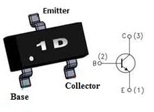
The pin configuration of the KST42 Transistor with a symbol is shown below. This NPN transistor includes three pins which are discussed below.

KST42 Pin Configuration
- Pin1 (Emitter): This pin is connected to GND, so the flow of current drains out throughout this pin.
- Pin2 (Base): This pin is used to control the transistor biasing, so it turns ON/OFF the transistor
- Pin3 (Collector): This pin is usually connected to a load, so current supplies throughout the collector terminal.
Features & Specifications:
The features & specifications of the KST42 transistor include the following.
- Type of transistor – NPN Type.
- The code of the SMD transistor is 1D.
- The transistor material is Si.
- It is available in the SOT23 SMD package.
- Its current gain or hFE is 40.
- Its minimum transition frequency is 50 MHz.
- Its collector dissipation is 0.35 W.
- Its continuous maximum collector current is 0.5 A.
- The operating & storage junction temperature ranges from 55 to +150 °C
- Its continuous collector current or IC is 500mA.
- Its collector emitter voltage or VCEO is 300 V.
- Its collector-to-base voltage or VCB0 is 300V.
- Its emitter-base voltage or VBE0 is 6Volts.
- Its transition frequency is 50MHz.
- Its maximum collector-to-emitter voltage is 300 V.
- Its maximum collector-to-base voltage is 300 V.
- Its maximum emitter to base voltage is 6V.
Equivalent/ Replacement Transistors:
Equivalent KST42 transistors are; FJV42MTF, CHT42GP & STR1550, and KST42 transistors can be replaced with the PBHV8540T/STR1550 and MMBTA42. The complementary KST12 NPN transistor is the KST92 PNP transistor. To know how to replace it, please refer to this; Replacing Transistors in Electronic Circuits: Factors and Considerations.
How to safely use the KST42 Transistor in a Circuit?
To use KST42 Transistor very securely in a circuit for a long time, its temperature range should be above 55 to below +150 °C. Its collector-to-emitter voltage should not exceed to 300V & collector current to above 500mAThis transistor pins must be used with exact directions because an incorrect pin connection can lead to transistor damage. Connecting a resistor to the base terminal of the transistor is a practise to protect it from damage. Please refer to this link for; Choosing Base Resistance for Transistors in Electronic Circuits.
Before using any of the transistors within a circuit first, we need to know how to choose a transistor for a circuit. Click this link How to Select a Transistor to know about it.
LED Tube Light Controlled by KST42:
In LED tube light, current controlling is very significant because light-emitting diodes are current-sensitive devices & they can enter thermal runaway situations very fast, so they can be damaged permanently. To avoid this situation, current control is very important for any LED driver circuit.
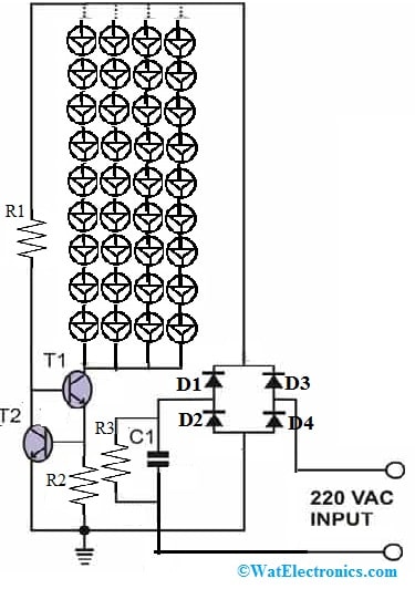
The required components to make this circuit mainly include 2 uF/400 V C1, T1 & T2 = KST42, 1N4007 Diode, and resistors. Connect the circuit as per the circuit diagram shown below.

LED Tube Light Controlled by Current Circuit
Working
Once input AC is provided to the above circuit, then C1 will reduce the input current so this current is considered a safe current for the circuit operation. The diodes in this circuit will rectify the low AC current and supply it to the next current-detecting stage which includes T1 and T2 transistors.
At first, the T1 transistor is biased throughout the R1 resistor & completely conducts to illuminate the whole LED array. If the flow of current delivered through the T1 transistor or current drawn through the LEDs is in the particular limit, then the T2 transistor will stay in a non-conducting mode, but the current drawn through the LEDs starts to cross this limit and the voltage across the R2 limiting resistor starts to build up some voltage across it.
Once this voltage goes above 0.6, the T2 transistor starts to leak throughout its collector to emitter pins. Since the T2 transistor’s collector terminal is connected to the T1 transistor’s base, the biasing current toward the T1 transistor starts leaking toward the ground terminal.
So this reduces the T1 transistor from conducting completely & its collector current will stop increasing. Since the light-emitting diodes form the collector load of transistor T1, the flow of current throughout these LEDs also gets controlled & the devices are protected from the increasing current.
The above current increases whenever the input AC current increases and also equivalent increases within the LED current consumption, however, the addition of T1 & T2 will ensure that anything that’s unsafe to the LEDs is efficiently controlled and restricted.
A transistor can also be interfaced with a microcontroller. Read on Interfacing Transistor to microcontroller and also check on the precautions need to be taken before interfacing a transistor to microcontroller.
Where to use KST42 Transistor/Applications
The applications of the KST42 transistor include the following.
- KST42 transistor is used in high-voltage switching-based applications.
- It is used in microphone amplifiers.
- This transistor is used in low-power amplifiers.
- These are used wherever low on-state resistance is necessary.
- It is used in power management-based applications.
- This general-purpose transistor is used for both switching as well as amplification purposes.
- It is used in switching high-voltage applications.
- This PNP transistor is applicable in low audio amplifier-based designs due to its 40 gain value.
- These transistors are used in designing amplifier circuits & push-pull circuits by combining their complementary transistor.
Please refer to this link for KST42 Transistor Datasheet.
Thus, this is an overview of a high voltage transistor like a KST42 transistor, pin configuration, features, specifications, application circuit, working, and its applications. Here is a question for you, what is KST43 transistor?