Klystron Amplifier
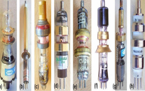
The term “Klystron amplifier” was designed by two brothers, namely Sigurd Varian and Russell at Stanford University.The prototype and the demonstration of this amplifier is finished successfully on 30th august 1937 and published in the year 1939. News of the klystron amplifier was influenced by the US and UK researchers which are working on radar device. These amplifiers are one type of microwave vacuum tubes which are used as an amplifiers in some radar devices as amplifiers. These amplifiers make use of the transit time influence by changing the velocity of an electron beam. These amplifiers use cavities to modulate the electric field nearby the axis of the tube.
Klystron Amplifier
A klystron amplifier is a specific linear-beam vacuum tube, which is used as an amplifier for high resonant frequencies. The term ‘klys’ comes from the stem form of a Greek verb mentioning to the wave action breaking against a shore. And the suffix ‘tron’ is the place where the action occurs. The name of this amplifier was recommended by a professor “Hermann Fränkel” in the department of classics from the Stanford University when the amplifier was under progress.

Klystron Amplifier
In this amplifier, an electron beam relates to the radio waves as it passes via metal boxes, resonant cavities along with the length of the tube. The signal of the amplifier can be amplified by the energy of the electron beam and the amplified signal can be received from a cavity at the other end of the tube.
The o/p signal can be joined back into the i/p cavity to make an electronic oscillator to produce radio waves. The gain of this amplifier can be 60 dB (one million) or above, with o/p power up to tens of mw. But the bandwidth of this amplifier is narrow, usually it can be up to 10% in some equipments.
Types of Klystron Amplifiers
Klystron amplifiers are velocity modulated and high power microwave vacuum tubes which are used as an amplifiers in some radar devices. These devices make use of the transit time effect by changing the electron beam’s velocity. A klystron includes one or more cavities, which control the electrical field around the axis of the tube. Based on the resonant cavities, klystron amplifiers are classified into two types.
- Two cavity klystron amplifier
- Reflex klystron amplifier
Two Cavity Klystron Amplifier
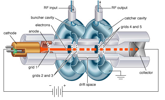
A klystron amplifier uses different cavities which control the electric field around the axis of the tube. A grid is placed in the middle of these cavities to allow the electrons to flow. The first cavity together with the coupling device is termed as a ‘Buncher’. In the same way, the second cavity with coupling device is called as a ‘Catcher’.The field direction changes with the frequency of the Buncher cavity. These changes, substitute hurry and slow the electrons of the beam flowing through the grids. The space outside the Buncher grids is called the drift space. The Bunches can be formed by the electrons in this area when the faster electrons overtake the slowed electrons.

Two Cavity Klystron Amplifier
Here, the catcher cavity is used to absorb energy from the electron beam.. The catcher grids are located with a bean, at a place where the Bunches are totally formed. The place is determined by the transit time of the bunches at the natural RF of the cavities. The collector receives the energy of the electron beam and alter it into heat as well as X-radiation. The addition of an intermediate cavity b/n the i/p and o/p cavities of the basic klystron can be improves the power o/p, efficiency and klystron amplification. Extra cavities serve to velocity modulate the electron beam and generate an increase in the energy available at the o/p.
Reflex Klystron Amplifier
The reflex klystron is also called as Sutton tube invented by Robert Sutton. It is a low power tube with a single and work as an oscillator. The reflex klystron amplifier is used as an oscillator in a modulator in microwave transmitters and radar receivers. But, these devices are replaced by semiconductor microwave devices.
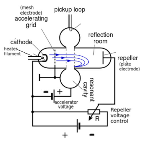
In this type of klystron amplifier, the electron beam flows through a single resonant cavity. The electrons in this amplifier are excited by an electron gun into one end of the tube. After permitting through the resonant cavity they are replicated by a negatively charged reflector electrode for an alternative pass through the cavity, where they are then composed.

Reflex Klystron Amplifier
When the electron beam is flowing through the cavity, then it is velocity modulated. The making of electron bunches takes place in the drift space between the cavity and reflector. The voltage on the reflector must be attuned so that the bunching will be at maximum as the electron beam returns the cavity, therefore confirming a max of energy is moved from the electron beam to the RF oscillations in the cavity.
The reflector voltage may be changed somewhat from the optimum value, which effects in some loss of o/p power, but also in a difference in frequency. This result gives an advantage for controlling of an automatic frequency in receivers, and in FM (frequency modulation) for transmitters.The modulation level which applies to transmission is small enough that the o/p power basically remains constant. At sections far from the optimum voltage, no oscillations are found at all.
There are frequently numerous regions of reflector voltage where the reflex klystron amplifier will oscillate; these are denoted with modes. The range of electronic tuning for the reflex klystron is usually denoted with the change in frequency b/n half power points. The half power points in the oscillating mode where the o/p power is half the maximum o/p in the mode. In most applications, reflex klystron is effectively replaced by the modern semiconductor technology.
Applications of Klystron Amplifiers
The applications of klystron amplifiers are
- These amplifiers can generate far higher microwave power o/ps than solid state microwave devices like gunn diodes.
- Klystron amplifiers are used in modern systems, they are used from hundreds of MHz (UHF) through hundreds of GHz.
- These amplifiers can be found in satellite, radar, wideband high-power communication, medicine, high-energy physics.
- At SLAC, these amplifiers are normally employed which have o/ps in the range of 50 MW & 50 kW (time-averaged) at 2856 Mega Hertz.
- The Radar uses two klystrons that offer a total o/p power of 1 MW at 2380 Mega Hertz.
- Global Resource Corporation (GRC) currently using a klystron amplifier to convert the hydrocarbons in daily materials, coal, automotive waste, oil sands, diesel fuel, oil shale and oil sands intonatural gas.
Thus, this is all about the klystron amplifier, types of klystron amplifiers and applications. We hope that you have got a better understanding about this concept. Furthermore, any queries regarding this concept, please give your valuable suggestions by commenting in the comment section below.Here is a question for you, what is the function of Klystron Amplifier?
Photo Credits:
- Klystron Amplifiers radiomuseum
- Klystron Amplifier wiki2