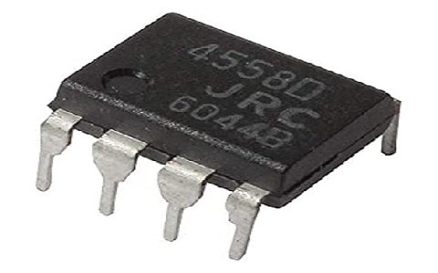
The JRC4558 IC is a dual op-amp by Japan Radio Company which is compensated & designed with bipolar transistors internally on a single silicon chip. These ICs are perfect in pedal circuit designs due to their high voltage gain, good input impedance & versatile power supply. This op-amp has industry standard pin configuration which means there are various IC suppliers manufacturing devices that are 4558 pin compatible The first monolithic RC4558 dual op-amp was developed by Raytheon Semiconductors in the year 1974. This IC was preferred by Japanese design engineers in Japanese audio equipment because it was one of the low-cost dual op-amps with adequate audio performance. This article provides brief information on the JRC4558 op-amp, pinout, specifications, and its applications.
What is the JRC4558 Op-Amp?
The JRC4558 IC is a monolithic dual op-amp-based silicon chip that is available with good input impedance & high voltage gain. This IC includes two independent, internally frequency compensated & good input impedance-based operational amplifiers that are designed very carefully to run above a wide range of voltages using a single power supply. The output signal provided by JRC4558 op-amp is much larger as compared to the potential variation at the input. This IC is designed carefully and needs simply a 5V normal voltage supply to function within electrical and electronic circuits.

JRC4558 Op Amp
Pin Configuration:
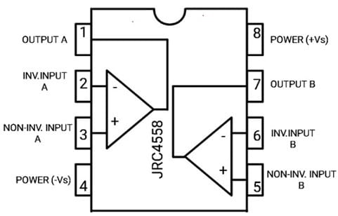
The pin configuration of the JRC4558 op-amp is shown below. This IC includes 8 pins which are discussed below.

JRC4558 Pin Configuration
Pin-1 (OUT-A): This is the output pin of the first op-amp.
Pin-2 (Inverting Input-A): This is the Inverting i/p pin of the first op-amp.
Pin-3 (Non-Inverting Input-A): This is the non-inverting i/p pin of the first op-amp.
Pin-4 (Power (-Vs)): This is the negative supply terminal or GND.
Pin-5 (Reference): This is the non-inverting i/p pin of the second op-amp.
Pin-6 (Output): This is the inverting i/p pin of the second op-amp.
Pin-7(Power (+Vs)): This is the o/p pin of the second op-amp.
Pin-8 (+VS): This is the positive (+ve) supply terminal.
Features & Specifications:
The features and specifications of the JRC4558 op-amp include the following.
- It is an 8-pin op-amp.
- The bandwidth of this op-amp is 3MHz.
- This IC includes two operational amplifiers internally.
- It doesn’t need frequency compensation.
- It is available in 8-pin DIP & SOP Packages.
- Its operating temperature ranges from 0°C to 70°C.
- Its input impedance is 5 MO.
- Its voltage supply ranges from ± 5Volts to ± 15Volts.
- Its voltage gain is 100 dB.
- Its slew rate is 1.7V/µs.
- It is available with 3MH Bandwidth.
- It is compatible with MC1458/LM358.
- It has a large common mode & differential voltage range.
- This IC provides a parameter tracking above the particular range of temperature.
- There is a match of phase & gain between the two op-amps.
- It has input transistors with low noise.
Equivalent & Alternatives
The equivalent JRC4558 op-amps are; NE5532, OPA2134, TL072, etc. The alternatives JRC4558 op-amps are; LM158, LM158A, LM358A, LM2904Q, LM358, LM2904, LM4558 & LM747.
How to Long Run JRC4558 IC Securely within a Circuit ?
It is suggested to stay always JRC4558 IC under its max ratings to obtain the best performance for the long term. Do not apply above 15V to the op-amp IC; avoid the terminals of the op-amp from being short-circuited. This IC must be stored in a temperature > -65 degrees C < +150 degrees C. The operating temperature of this IC must range between -25 degrees C to +85 degrees C.
There are few points that need to be considered before choosing an op-amplifier. Read on How to choose an operational amplifier ?
Current Loop Tester Circuit with JRC4558 Op-Amp
In any measurement system, sensors play a key role by helping to modify the different parameters in the real world into electronic signals that can be understood through machines. Analog and digital sensors are commonly used in the industrial sector. Analog sensors communicate with variable voltage or current whereas digital sensors communicate with 1’s & 0’s with different protocols like I2C, USART, SPI, and many more.
The analog voltage sensors are connected with V to I converters for changing the analog voltage to analog current to turn into a variable current sensor. So this kind of sensor follows the 4 to 20mA protocol, which means this sensor will provide 4mA of output whenever the value measured is 0 & will o/p 20mA whenever the value measured is highest. If the output of the variable current sensor is below 4mA or above 20mA then we can assume it the sensor is in a faulty condition.
The calibration of analog voltage sensors within industries is a routine procedure. To calibrate the system & also to troubleshoot the results of errors, current loop testing is used. So in this testing process, it utilizes a verification process that verifies breakage within the communication line & also the transmitter o/p current.
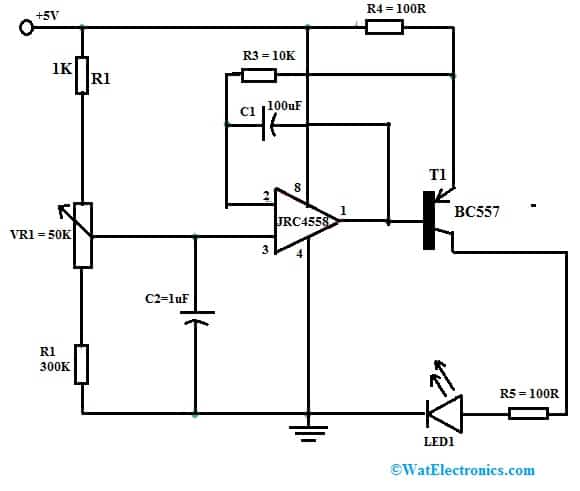
Here, a basic current loop tester circuit is designed with a few electronic components to allow us to adjust current manually from 4Aa to 20mA by rotating a potentiometer. The required components to make this circuit are; a 5V power supply, BC557 PNP transistor, JRC4558 op-amp, 300k resistor, 1k resistor, 50k 10 turn potentiometer, 100pF, 1uF, 100R resistor, any color LED hookup wire & a multimeter to measure the Current. Connect the circuit as per the diagram shown below.

Current Loop Tester Circuit with JRC4558 Op-Amp
Working
This circuit includes a JRC4558 op-amp that drives a BC557 PNP transistor. This transistor’s output current is given to an LED. The o/p current can be changed from 0mA-20mA by changing the potentiometer & can be measured through an Ammeter. Here, the JRC4558 op-amp works as a current source through negative feedback. The i/p variable voltage is provided to the Op-Amp’s non-inverting pin with a potentiometer. The highest output current like 20mA can be set through the resistor which is connected to the op-Amp’s inverting pin.
Here the JRC4558 op-amp will bias the BC557 transistor to supply a constant current throughout the LED based on the supplied voltage to the non-inverting pin from the potentiometer. The LED in this circuit is used as the load & the current loop circuit provides the necessary current toward the LED. The current to the load is supplied through the transistor and is controlled directly by the 4558 op-amp.
On the op-amp +ve input, a reference voltage is supplied by the potentiometer. So based on the reference voltage, here the amplifier provides simply the bias current to the base terminal of the transistor. Here an extra series resistor is connected across the potentiometer to limit the reference voltage & also the amplifier’s output to create the edge of 0mA – 20mA. The min to max output current boundary can be changed by changing the resistor value.
The main application of a 4-20mA current loop tester is to test or calibrate the PLC machines that receive 4-20 mA protocol and provide data depending on it. Therefore, the wrong calibration resulted in the error value perceived by the PLC. Not only calibration, But it is also a convenient process to check the current loop breakage.
The 4 to 20mA current loop circuit applications mainly include control systems & industrial automation. This 4-20 mA communication line is used by the position of the valve, water flow, production of oil, and the associated sensors used for the process of production. This is also helpful in finding & also debugging fault conditions in the industry to save money & time. This current loop tester is a crucial tool for resolving sensor-based issues.
The main drawbacks of this circuit are; that this circuit must include a variety of protection circuits; surge protection & short circuit protection across all input & output which is appropriate to utilize in industrial environments because the industrial environment is extremely harsh as compared to the lab environment.
Applications
The applications of the JRC4558 op-amp include the following.
- JRC455 op-amp is used in amplification blocks, transducer amplifiers & single-supply voltage systems.
- These operational amplifiers are used in analog circuits due to their versatility.
- These are extensively used in industrial, consumer & scientific device applications.
- This amplifier is extensively used in pedal circuits & sample & hold amplifier designs.
- These ICs are used in intrusion alarms & portable instrumentation systems.
- These op-amps are used in multivibrators or long-duration timers.
- These ICs are used in intrusion alarm systems, photocurrent instrumentation, function generators & comparators.
- This IC is used in general-purpose op-amps circuits like comparator and differential amplifiers.
- These op-amp ICs are used by engineers & hobbyists due to their lower cost & good performance.
- These op amps are used in preamplifier circuits and current loop tester circuits.
Please refer to this link for the JRC4558 Op-Amp Datasheet.
Thus, this is an overview of the JRC4558 Op Amp. JRC4558 IC is an 8-pin dual op-amp general-purpose amplifier including good input impedance & significant voltage gains. This is an integrated silicon monolithic chip available in SOP & DIP packages so used widely in pedal circuits because it provides a very high-frequency gain & 5MΩ of input impedance. This IC is used by engineers as well as hobbyists due to its lower cost & superior efficiency and is also used as a universal op-amp in different electronic circuit applications. Here is a question for you, what is OPA2134 op-amp?