MOSFET driver is a voltage-controlled device used to change the logical signals of CMOS/TTL to a high voltage & high current by quickly & completely switching the MOSFET gate. MOSFET driver is arranged as a low-side and high-side switch. There are different kinds of MOSFET drivers in the market but in most applications, but mostly used high-low side MOSFET drivers are like IR2110 MOSFET driver IC. This article discusses an overview of the IR2110 MOSFET driver, its working, and its applications.
What is the IR2110 MOSFET Driver?
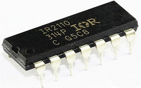
IR2110 MOSFET driver IC is a high-voltage IC that drives both high-side & low-side switches within low-bridge & half-bridge circuits. The IR2110 is a high voltage and high speed-based power MOSFET with independent low & high side referenced o/p channels. The logic inputs of this driver IC are compatible with typical LSTTL or CMOS outputs. The latch-immune CMOS & Proprietary HVIC technologies allow rugged monolithic construction. This IC’s operating voltage ranges from 10V to 20V, the maximum o/p current is 2.5A & supply current of this IC is 340µA.

IR2110 MOSFET Driver IC
Pin Configuration:
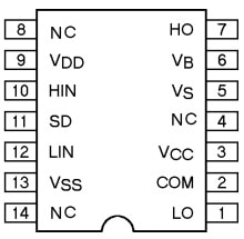
The pin configuration of the IR2110 MOSFET Driver is shown below. This IC includes 14 pins which are discussed below.

IR2110 IC Pin Configuration
- Pin 1(LO): It is a low-side gate driver’s o/p pin.
- Pin 2 (COM): It is a return path for low-side configuration.
- Pin 3 (VCC): It is a power supply pin for the low side.
- Pin 4, 8 & 14 (NC): These are not connected pins.
- Pin 5 (VS): It is a return path floating-point pin for the high-side drive.
- Pin 6 (VB): It is a floating supply pin used for high-side drive.
- Pin 7 (HO): It is an o/p signal pin used for high-side MOSFET.
- Pin 9 (VDD): It is a +5V power supply pin. Its value must be 5V, but. if you utilized voltage below 4 V then it may not provide you the necessary result.
- Pin 10 (HIN): It is a PWM signal i/p used for high-side drive.
- Pin 11 (SD): It is a shutdown pin used automatically to turn off the system.
- Pin 12 (LIN): It is a PWM signal i/p for a low-side drive.
- Pin 13 (VSS): It is a power supply GND pin.
Features & Specifications:
The features and specifications of the IR2110 MOSFET driver include the following.
- This MOSFET driver includes 14 pins.
- It is available in PDIP & SOIC packages.
- It is dV/dt immune.
- Under voltage lockout for two channels.
- Pull down CMOS Schmitt-triggered inputs.
- Shutdown logic is edge-triggered with cycle by cycle.
- The propagation delay is matched for both channels.
- Outputs are within phase by inputs.
- It is compatible with 3.3 V logic.
- Gate drive supply ranges from 10 – 20 V.
- Separate logic supply ranges from 3.3 V- 20 V.
- Logic & power ground is + /- 5 V offset.
- Its output current is 2.5A.
- Its voltage supply ranges from 10V- 20V.
- Its rise and fall time is 35 ns & 25 ns.
- The turn-On delay time max is 120 ns.
- Turn-Off delay time min is 94 ns.
- Its operating current supply is 340 µA.
- Equivalent IR2110 MOSFET drivers are; MIC4608, UCC27714 & FAN7392.
IR2110 MOSFET Driver Circuit
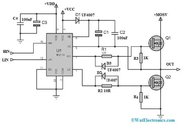
The IR2110 MOSFET driver in the half-bridge circuit is shown below. In many applications like in bridge circuits, MOSFET is configured as high-side and low-side switches. In half-bridge circuits, one high-side and one low-side MOSFET whereas in full-bridge circuits, two high-sides and two low-side MOSFETs are used. So in those situations, high-side drive circuitry is used next to low-side drive circuitry. The most common method to drive MOSFETs is to utilize high-low side MOSFET drivers like the IR2110.
The following circuit shows the common configuration of IR2110 to drive MOSFET in both high & low-side configurations. The required components to make this circuit mainly include an IR2110 MOSFET Driver IC, two MOSFETs Q1, Q2, diodes D1, D2 & D3, and capacitors C1 to C 4. Connect the circuit as per the circuit diagram shown below.

IR2110 MOSFET Driver Circuit
Working
In this circuit, the bootstrap circuit can be formed with a diode D1 and capacitors C1 & C2 with the IR2110 MOSFET driver. Once LIN = 1 then a signal can drive the low side of MOSFET, Q2 will be turned on & capacitors like C1 & C2 will get charged to the VB level, which is one diode drop under +Vcc.
Once LIN = 0 & HIN = 1, then a signal drives the high side of MOSFET, C1 & C2 capacitors will get changed which is used for adding the additional voltage that is equivalent to VB on the Q1 source level to drive the Q1 within the high-side MOSFET configuration. Here for C1, a large sufficient capacitance should be selected so that it supplies the necessary charge to maintain Q1 turn on continually.
To maintain the MOSFET ON, the capacitor C1 should not be too large & the level of voltage does not increase sufficiently to maintain the MOSFET ON. When the on-time is higher, the required capacitance will be higher. Therefore, if the frequency is low then the required C1 capacitance will be higher.
The diodes D2 & D3 in the circuit discharge the MOSFET’s gate capacitances very quickly bypassing the gate resistors and decreasing the turnoff time. Here, R1 & R2 are the gate current-limiting resistors, and the maximum +MOSV is up to 500V. For filtering, the decoupling and filter capacitors from +VCC to GND must be used.
The R4 resistor in the circuit is the Gate to source resistor. So it is very significant in the circuit to avoid the failing/burning of MOSFET or MOSFET driver IC damage. Here, Gate to source resistors avoids the chance of turning on the MOSFET through external noise generally whenever the gate is floating. Sometimes the MOSFET may turn on through a floating gate due to the inside drain (D) to gate (G) Miller capacitance. A gate (G) to source (S) resistor works like a pull-down to make sure a low level mainly for the MOSFET.
Applications
The applications of the IR2110 MOSFET driver include the following.
- High-Speed Switching:
- The IR2110 is capable of providing fast switching times, which is crucial in applications where quick response times are required. This is especially important in power inverters, motor drives, and other systems where efficient switching helps reduce power losses and improve overall system performance.
- Isolation and Protection:
- The IR2110 often includes features for providing electrical isolation between the input (control side) and the output (high-power side) of the circuit. This isolation helps protect sensitive control circuitry from high voltages and reduces the risk of damage to the control components.
- Driving Half-Bridge and Full-Bridge Configurations:
- The IR2110 is commonly used in half-bridge and full-bridge configurations, where multiple MOSFETs are arranged to control power flow in both directions. The IC is capable of driving complementary pairs of MOSFETs in such configurations, making it suitable for various power electronics applications.
- Motor Control Applications:
- In motor control systems, the IR2110 is often employed to drive MOSFETs that control the power supplied to the motor. Its high-speed switching capability is beneficial in achieving precise control of motor speed and direction.
- Switching Power Supplies:
- The IR2110 is used in the design of switching power supplies, where it helps efficiently regulate and control the flow of power to achieve desired output voltages.
- Pulse Transformer Compatibility:
- The IR2110 is designed to work with pulse transformers for signal isolation. This is particularly important in applications where electrical isolation is required for safety or operational reasons.
- IR2110 is the most frequently used low and high-side driver IC configured as a high-side & low-side switch.
- This MOSFET driver is normally used to operate power converters.
- This IC is a high-speed & high-voltage gate driver ICs for power MOSFET & IGBT.
- It is used in a sine wave inverter.
- It is used for a three-phase induction motor as a soft starter.
- Used in half and full bridge motor drivers.
- Used in industrial controls & white goods.
- The IR2110 is suitable for power converters, high power & motor control applications.
- This is very famous for driving H-bridge for isolated chargers & inverter applications.
- IR2110 MOSFET driver is used to control high-power devices because it is a high speed & high voltage device.
- The IR2110 is a popular choice for motor control, power converters, and other high-power applications.
- This IC is used for driving low & high-side configurations within low-bridge & half-bridge circuits
Please refer to this link for IR2110 MOSFET Driver Datasheet.
Thus, this is an overview of the IR2110 MOSFET Driver, pin configuration, specifications, and its applications. The IR2110 MOSFET driver IC is a powerful & flexible gate driver, used in a wide range of applications. It is a cost-effective & reliable solution for high voltage-based power switching applications. Here is a question for you, what is MOSFET?