Generally, automobiles (especially 2-wheeler and 4-wheeler vehicles) and security monitoring systems are equipped with multiple sensors that constantly monitor their operation and condition. Some sensors measure air, oxygen, and temperature, while others, such as knock sensors, measure vibration and noise levels in the vehicle’s engine and security monitor systems. Knock sensors, on the other hand, have a much wider range of applications and are also known as piezoelectric sensors Or vibration sensors. This article discusses on interfacing knock sensor to a microcontroller using Arduino to detect the knock or vibrations in security monitor systems like door knock monitoring systems.
Knock Sensor
The Knocks are the sounds and reactions that occur when an unexpected explosion or ignition takes place in the cylinder, apart from the regulated normal ignition of the ignition or spark plug. To detect these abnormal vibrations and sounds, a listening electronic device called a knock sensor is required.
The knock sensor monitors and detects the unusual vibrations and sounds from the engine block and then converts them into an electronic signal and sends it to the ECU (Engine Management Unit). Then the system in the automobile evaluates the data and checks whether the timing of the ignition should be adjusted or not. To prevent the damage or failure of the system or vehicle, it illuminates the CEL (Check Engine Light) or turns OFF the components in it.
Now, we are going to discuss on knock sensor as a security monitoring applications like door knock monitoring systems.
If any vibration is detected, then it goes to the close state for that instance and again returns to its normally open state. It is also called a tap sensor.
The different components of knock sensor modules are available in the market. They are KY-031, KY-029, KY-016, and KY-011. Among these KY-031 knock sensor modules is the most widely used module because it is available at affordable rates.
Pinout
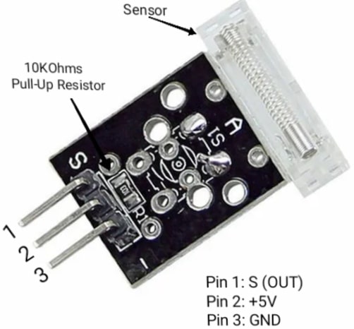
A KY-031 knock sensor is a 3-pin sensor module operating between 3.3V and 5.5VDC. The 3-pins of the knock sensor are GND, +5V, and S(OUT) or Signal (OUT).

Knock Sensor Module
- GND: It is a common ground connection of the sensor module.
- S(OUT): It represents the output signal.
- +5V: It represents the positive power supply of the sensor module.
The other components of the knock sensor module are a sensing element called a conductive vibration spring, which acts as a switch, and a pull-up resistor of 10KOhms. The knock sensor module is shown in the figure below. It is reliable and available in small sizes.
Knock Sensor Working
Knock Sensors Or Crash detection sensors are very popular in applications that want to ensure the safety of equipment or the people using it in the event of an excessive or crash vibration that could damage one of them. The knock sensor module KY-031 does the same.
It has a glass-encased wire that completes the circuit and breaks the circuit when the vibration exceeds a certain limit and sends a signal to an output pin that can be read by a microcontroller like Raspberry Pi, Arduino, ESP32, ESP8266, etc. To understand the working of Knock Sensor, consider the following circuit diagram given below.

Knock Sensor Circuit Diagram
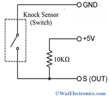
If you look at the above knock sensor circuit, it consists of a 10KiloOhms pull-up resistor and a switch. The vibration spring is shown as a switch. The output pin (S out) of the sensor, connected to one terminal of the switch, is driven HIGH by a 10 KiloOhms pull-up resistor. In normal conditions without knock or vibration, the knock sensor output becomes HIGH. When the sensor detects vibration or shock, the switch or vibration spring closes and the knock sensor output becomes LOW.
To know how the knock sensor works, consider an example of a door-knocking system. Attach the knock sensor to the door and knock on the door. If the vibration is sufficient to be detected by the sensor, the sensor output goes low for that time. To know if it is working fine connect the output to an LED with a pull up resistor and power supply. When the knocking goes above certain threshold LED will glow. In the next section let see how it works in an engine.
How to Connect Knock Sensor To a Microcontroller/ Interfacing Knock Sensor to Arduino
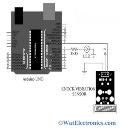
The circuit diagram of the knock sensor interfacing with a microcontroller using Arduino is shown below. The components required are;
- Arduino UNO board
- 1KOhms resistor.
- LED.
- Knock sensor.

Knock Senor Interfacing
Here the LED turns ON by an Arduino UNO only when the vibrations in the engine are detected by the knock sensor. The microcontroller used in this interfacing circuit is ATMEGA328P.
Knock sensor or Vibration Sensor Module
Now, let’s see how to connect the knock sensor to a microcontroller in an Arduino board. The knock sensor’s data (whether knocking or not) gets displayed on the serial monitor of the Arduino IDE.
Connections are made as per the above circuit diagram. The +5V pin of the knock sensor module is connected to the +5V supply pin of Arduino. The GND pin of the sensor module is connected to the ground (GND) pin of the Arduino. The SIGNAL (OUT) / S-pin of the knock sensor is connected to digital pin 8 (PB0/ICP1/CLK0 pin of ATMEGA328P) of Arduino UNO. And to detect the vibrations connect the LED to pin 7 (PD7/AIN1 pin of ATMEGA328P) of the Arduino via current limiting resistor 1k Ohms as shown in the above circuit.
The interface is equipped with digital LEDs. When the knock sensor detects the amount of the knock signal, it taps the signal and provides the information to the microcontroller connected and the LED indicator flashes.
Code for interfacing Knock Sensor with Arduino is shown below:
const int knockPin = 8; (S(OUT) pin of the sensor module is connected to pin 8 of Arduino.
const int ledPin = 7; (LED is connected to pin 7 in series with a pull up resistor)
int knockVal = HIGH;
boolean knockAlarm = false;
unsigned long prevKnockTime;
int knockAlarmTime = 100;
void setup ()
{
Serial.begin(9600);
pinMode (ledPin, OUTPUT) ;
pinMode (knockPin, INPUT) ;
}
void loop ()
{
knockVal = digitalRead (knockPin) ;
if (knockVal == LOW)
{
prevKnockTime = millis();
if (!knockAlarm)
{
Serial.println(“KNOCK, KNOCK”);
digitalWrite(ledPin,HIGH);
knockAlarm = true;
delay(1000);
}
}
else
{
if( (millis()-prevKnockTime) > knockAlarmTime && knockAlarm)
{
digitalWrite(ledPin,LOW);
Serial.println(“No Knocks”);
knockAlarm = false;
}
}
}
Know more about Control Unit MCQs.
Thus, this is all about an overview of the knock Sensors (KY-031). You can set the delay time or output frequency for the program logic to activate the corresponding safety device. The module can be powered by both 5V and 3.3V and is very easy to use. But it is not applicable for real-time applications. Here is a question for you, what is the function of a proximity sensor?