During the 1960s, HP developed many different tests and measuring devices like logic analyzers and multimeters. In order to achieve smoother interconnection between controllers and measuring instruments, the HP-IB was introduced (HP Interface Bus). HPIB is the original name for GPIB (General Purpose Interface Bus), whereas later it got many other names. Finally, the Institute of Electrical and Electronics Engineers has provided a specification number to GPIB which is 488 in the year 1978. From then, GPIB was also termed IEEE 488 or IEEE 488 bus. Today, this article helps us in understanding the detailed concept regarding the basics of GPIB, its architecture, working principles, and advantages & disadvantages.
What is GPIB or IEEE 488 Bus?
The IEEE 488 (GPIB) bus is an 8-bit parallel multi-master interface bus that is used for short-distance communications. As the bus became the key interface meeting multiple standards, it was termed as General Purpose Interface Bus. Because of its flexibility, the data transmission can take place between any instruments present in the bus having a speed appropriate for the slowest active instrument.
Achieve proper communication between the devices in GPIB requires three components which are:
Talker – This holds the ability to transmit device-dependent information from one device to another device on the bus when it is addressed to talk. On the whole device, only one GPIB instrument can function as an active talker at a time.
Listener – It is responsible to receive device-dependent information from another device present in the bus when it is addressed to listen. On the whole device, more number of GPIB instruments can function as active listeners at a time.
Controller – The name of the controller itself signifies that it is an entity that manages the entire functionality of the bus. The controller is generally a computer that provides the signal to the instruments to execute multiple activities making sure that no issues take place in the bus. When two talker devices try to talk at the same time instant, it leads to data corruption and shows the impact on the entire system.
IEEE 488 bus allows different controllers to share a similar bus whereas only one controller will be active at any specific time.
GPIB bus consists of eight data lines in order to transmit 8 bits of data at a single instance. And command messages work with seven bits out of 8 and the message format is shown below:

Message Format
Bits 0 through 4 indicate the primary address of the device, for which the Talker/Listener assignment is intended. If bit 5 is high, the device should listen. If bit 6 is high, the device should talk. Bit 7 is a “don’t care” bit. Its value is ignored, so it is interpreted as a value of zero in command messages.
IEEE 488 Bus Features
As the main functionality of GPIB is to establish interconnection between various instruments and devices, it is recommended to know the features of the IEEE 488 bus. A few of those are:
- The transaction between the messages is a hardware three-wire-handshake.
- Communication happens in digital format and it transmits only one byte of data at a time.
- To a single IEEE 488 bus, approximately 15 devices can be connected at a time.
- The bus length can be 20 meters, but the distance between each device can be 2 meters.
- The maximum data rates can be up to 1 Megabyte/second.
- The width of the data bus is 8 lines.
- The connector used in GPIB is a 24-pin Amphenol or sometimes a D-type connector is also used.
- The bus can support 31 5-bit primary devices which are addressed from 0-to 30 by assigning a unique address for every device.
- The topology used in GPIB is linear or forked type.
- The protocol supports both half-duplex and full-duplex communication modes so that two devices can send data while at the same time receiving data from each other simultaneously
IEEE 488 Bus Block Diagram
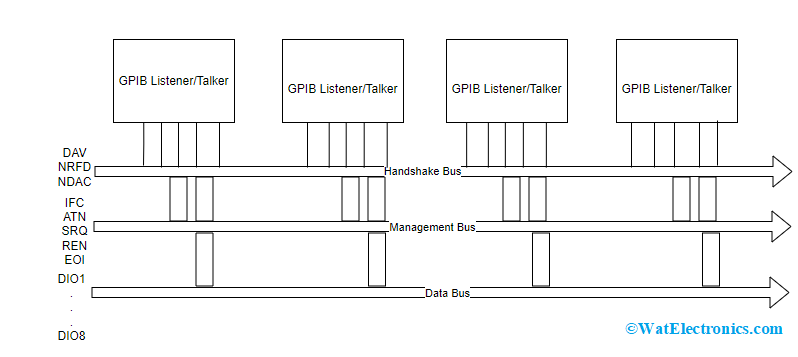
The IEEE 488 bus architecture, consists of 16 signaling lines that are used to carry information and allow to pass commands between various devices that have connections with the bus. These 16 signals are classified into three groups which are

IEEE 488 Bus Architecture
Data Bus – 8 lines, Data Byte Transfer Control Bus – 3 lines,s, and General Interface Management Bus – 5 lines.
All three functional groups explain the IEEE 488 bus working principle.
Data Bus
The data bus acts as a channel for data transmission and passage of commands across the device connected to the GPIB device. The 8 signals are named DIO 1 to DIO 8 which are bidirectional in nature and active low lines. The data transmission using the commands takes place in bit-parallel and byte-serial approaches which correspond that only one data byte can be transmitted at a time. DIO 1 is the LSB bit and DIO 8 is the MSB bit.
Every byte which is placed in the data bus denotes either a data byte or a command. At the time of data transmission, when the ATN pin is TRUE, then the data bus carries a command that is to be received by each device in the GPIB bus. Whereas when the ATN is FALSE while data transmission, then the data bus carries a data byte. Here, only the active listeners are able to receive the carried byte.
Data Byte Transfer Control Bus
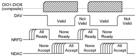
The control over data transmission of every byte that happens in the data bus can be achieved through an approach named “three-wired-handshake”. Using this approach, the data transmission happens at the speed level of the slowest listener so that every listener can be able to hear, ensuring data integrity.
The handshake signaling approach is explained below:
- Initially, the DAV signal will be made to LOW by the talker and observes the NRFD and NDAC lines which are regulated by the listener.
- On the DIO lines, data bytes are placed by the talker.
- Then the talker holds its time for NRFD in order to make the listener LOW.
- Now, the talker affirms the DAV line and the listener instantaneously affirms the NRFD which concedes to the talker that the present data bye is under process.
- Later, the listener receives the data byte and lows down the NDAC signal. At this time, the talker will make the DAV signal Low.
- In the process of the next byte to transmit, the listener makes NDAC high.
The DAV (Data Available) is managed by the talker, and the NRFD (Not Ready For Data) and NDAC (Not Data Accepted) which are wired-OR lines are shared by all the active listeners. All the three DAV, NRFD, and NDAC are active-low signals.

Handshake Process in GPIB
General Interface Management Bus
This is a group of 5 lines that controls the data flow all over the GPIB device. The functionality of each line is explained below:
ATN (Attention) – Every byte which is placed in the data bus denotes either a data byte or a command and ATN is used to decide whether the byte is a data byte or a command. When ATN turns low, the bus signifies command mode and when ATN turns HIGH, the bus signifies data byte mode.
EOI (End/Identify) – In the multi-byte data transfer, this bit signifies the last byte. At the time of the last data byte, the talker sets the EOI pin to TRUE. In order to start a parallel poll sequence, the active controller works along with the ATN line and EOI line.
IFC (Interface Clear) –This line is used only by the system controller. When the IFC line is LOW, all the devices which are placed on the bus are not addressed to listen, talk and even IFC Low makes the bus to be in a service request idle state.
SRQ (Service Request) – This pin transmits an interrupt request to the controller. The request indicates that there may be an issue or the device is ready to transmit thus making the SRQ line TRUE. This states to the controller that the device which has a connection with the bus is requesting a service.
As the controller will not be aware of which device is requesting a service, it creates a poll to find the device that requests the service and then analyzes the request.
REN (Remote Enable) – This line is used only by the system controller. When the REN pin is LOW (True), then the bus moves to a remote state, and the devices will be addressed either to talk or listen. When the REN pin is HIGH (False), the devices along with the bus returns to the local state.
Types of Message Transmissions in GPIB
There are mainly three types of message transmissions in the IEEE 488 bus.
Interface Function Transmission – The data flow over GPIB is mainly controlled by the controller through interface function messages which are termed commands. These messages execute the activities of addressing/unaddressing the devices, switching the device modes for local and remote functionality, and initializing the bus.
There exist two kinds of commands which are inline and multiline. The commands are said to be multiline in that the bytes are transferred by the active controller through DIO1 – DIO8 pins having the ATN line set as TRUE. Whereas the commands are said to be online when the signals are carried by the interface management bus.
Device Correspondent Commands – These are either the mnemonic codes or keywords transmitted by the external controller in order to regulate the functionality and setup of the addressed instrument. These commands are distinctive for each instrument. The device correspondent commands will transmit in ASCII pattern having codes/one or more keywords.
These ASCII format messages are then decoded by an internal controller in the device and allow multiple activities to be executed.
Data & Instrument Status Messages – Through the GPIB, the messages are transmitted to the external controller. These messages hold the data of device status, measurement output, or the data files that the device sends in response to corresponding requests from an external controller. The information present in the messages varies from device to device and is in the form of binary data/ASCII.
Connectors for GPIB
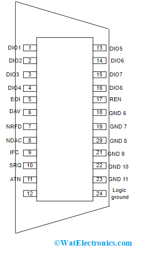
The standard connector used in IEEE 488 bus in 24-way Amphenol. This connector has a D shape metal shell but the size of 24-way Amphenol is more than D-subminiature connectors.

IEEE 488 Bus Connector
The below table details the pin configuration of the connector.
| GPIB Pin | Abbreviation | Line Name |
| 1 | Data Input/Output 1 | DIO1 |
| 2 | Data Input/Output 2 | DIO2 |
| 3 | Data Input/Output 3 | DIO3 |
| 4 | Data Input/Output 4 | DIO4 |
| 5 | End or Identify | EOI |
| 6 | Data Valid | DAV |
| 7 | Not Ready for Data | NRFD |
| 8 | Not Data Accepted | NDAC |
| 9 | Interface Clear | IFC |
| 10 | Service Request | SRQ |
| 11 | Attention | ATN |
| 12 | Shield (Connected to Earth) | |
| 13 | Data Input / Output 5 | DIO5 |
| 14 | Data Input / Output 6 | DIO6 |
| 15 | Data Input / Output 7 | DIO7 |
| 16 | Data Input / Output 8 | DIO8 |
| 17 | Remote Enable | REN |
| 18 | Twisted pair with pin 6 | Wire twisted with DAV line |
| 19 | Twisted pair with pin 7 | Wire twisted with NRFD line |
| 20 | Twisted pair with pin 8 | Wire twisted with NDAC line |
| 21 | Twisted pair with pin 9 | Wire twisted with IFC line |
| 22 | Twisted pair with pin 10 | Wire twisted with SRQ line |
| 23 | Twisted pair with pin 11 | Wire twisted with ATN line |
| 24 | Signal Ground |
Difference between GPIB and Ethernet
- Ethernet is a type of data communication protocol that uses a local area network (LAN) to transmit data between multiple devices whereas GPIB uses twisted pair cables similar to the one used for RS232C or RS422 to connect to devices.
-
The GPIB protocol uses differential driver signals for transmissions. This allows for high noise immunity and reliable transmission over long distances without requiring expensive shielded cabling whereas the Ethernet cables are multiple pairs and require an expensive shielding to avoid noises.
-
Ethernet is based on packet-switching technology, which allows for faster and more efficient communication between devices than parallel-wire systems like GPIB. While Ethernet does not offer the bandwidth of other networking technologies like ATM or FDDI, it is much easier to install and manage because it doesn’t require any special cabling or connectors between devices.
-
A single GPIB controller can control up to 63 instruments at once using the daisy chain method whereas Ethernet is able to connect more than 100,000 devices together using LAN technology.
Advantages and Disadvantages of IEEE 488 Bus
Here are the advantages and disadvantages of the GPIB bus.
Advantages
- This interface is widely used in most bench instruments.
- This bus allows connecting multiple instruments for a single controller.
- The hardware interface is not complex and standard also.
- The connectors that are used in the bus are rugged in nature.
- Shows enhanced performance levels.
Disadvantages
- These are hard to maintain as they occupy heavy spacing and are bulky too.
- When compared with modern-day interfaces, IEEE 488 bus offers minimal bandwidth.
- Because of heavy cables, the device exhibits less reliability.
- Used only for minimal-speed data transmissions.
- Its use is mostly limited to laboratories and manufacturing facilities where there are multiple instruments connected together.
IEEE 488 Bus Applications
A few of the applications of GPIB are:
- Used in computers and measuring devices.
- Employed for application debugging purposes.
- Used for RS232 interfacing.
What you have read so far is about a 20-year-old protocol for connecting instruments and control systems together and even used with PLCs. I hope this article has provided a clear explanation of IEEE 488/GPIB bus architecture, working principle, message formats, applications, and advantages. Know, how IEEE 488 bus can be used as a computer interface?