Analog to digital converter or ADC is used in different electronic devices like mobile phones, computers, etc to change the input signal from the physical world and changes into the binary format through ADC converters. There are different signals like sound & electricity which are available in different forms and shapes when they are in analog condition. So, analog to digital converter IC is used to modify & process them in nearly another way. ADCs are mainly used in various applications like radio, digital music, digital photography, etc. There are different types of ADC ICs available like ICl7107, ICL7106, ADC080 4, MCP3008, ADC0808, ADC0809, etc. This article discusses an overview of an ICl7107 ADC display driver – working with applications.
What is ICl7107 ADC Display Driver?
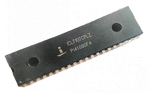
ICL7107 ADC display driver is a low-power, high-performance, and monolithic integrated circuit mainly used for analog to digital (A/D) conversions equal to 31/2 digits. This IC includes display drive circuitry that avoids the requirement of connecting an exterior drive circuit.

ICl7107 ADC Display Driver
This IC has quite a high input impedance, digital drivers, polarity, clock circuit, voltage reference, and segment decoders is also available on its board. This ADC IC utilizes a dual-slope conversion method that intrinsically declines interference signals from the atmosphere. The ICL7107 ADC IC drives directly a common anode LED display and the inbuilt features of these ADCs are accuracy & versatility. These ADCs are utilized in an extensive range of digital panel meter applications to measure & display analog data.
This ICL7107 ADC module has 3 ½ bit resolution, so it displays from 0 to 1999 digital value. The main specialty of this ADC IC is; it is available with an in-built four-digit 7-segment display driver. Thus to display the voltage measured we have to connect a seven-segment display to the ADC IC output.
Pin Configuration:
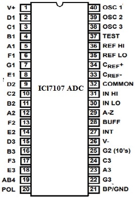
The pin configuration of the ICl7107 ADC display driver is shown below.

ICl7107 ADC Pin Configuration
- Pin1 (Supply voltage): This pin is used to provide the operating voltage for the ADC IC
- Pins 2,3,4,5,6,7 & 8 (4th digit of 7-Segment): All these pins are simply connected to the seven-segment display to display the once digit of the o/p value.
- Pins 9,10,11,12,13,14 and 25 (3rd digit of 7-segment): All these pins are used to connect to seven segments to display the 10th digit.
- Pins 15,16,17,18,22,23 & 24 (Second digit of 7-segment): All these pins of ICs are connected to seven segments to display the 100th digit.
- Pins 19 and 20 (1st digit of 7-segment): All these pins are connected to seven segments to display the 1000th digit.
- Pin21 (Ground): This pin is connected to the GND of the system.
- Pin26 (Voltage Supply): This pin is used to provide the negative voltage supply.
- Pin27 (Signal Integrate): This pin is used to connect to a capacitor.
- Pins 28 & 29 (Auto Zero & buff): These two pins are connected to a resistor & capacitor network.
- Pin 30 and 31 (i/p High & i/p Low): Here, the analog voltage is connected which has to be calculated.
- Pin32 (Common): This pin is connected to GND.
- Pins 33 & 34 (Cref+ & Cref-): Across these two pins, a capacitor is connected to neutralize fluctuations within reference voltage.
- Pins 35 and 36 (Reference High & Reference Low): These pins can either supply reference voltage otherwise utilize inside reference voltage
- Pin37 (Test pin): This pin is not utilized throughout the operation.
- Pins 38, 39, and 40 (OSC1, 2, 3): Utilize RC n/w top set oscillator frequency.
Features & Specifications:
The features & specifications of the ICl7107 ADC display driver include the following.
- This IC includes 40 pins with PDIP & MQFP packages.
- Its terminal finish is Matte Tin.
- The type of mounting is Through a Hole.
- It has tube packaging.
- Its MSL or moisture sensitivity level is 1 (Unlimited).
- The technology used is CMOS.
- Guaranteed zero (0) reading for zero volts i/p on all scales.
- Polarity is true at zero for exact null detection.
- Its typical i/p current is 1pA.
- It has low noise below 15µVP-P.
- It has On-chip CLK & reference.
- It has low power dissipation like below 10mW.
- It doesn’t need extra active circuits.
- It has improved display stability.
- It is a 3 ½ bit ADC module including four-digit seven-segment display driver.
- Its single voltage supply is 0 to 6V and its dual voltage supply is -15V to +15V.
- Its analog i/p voltage is equivalent to the voltage supply.
- It has an internal oscillator.
- Its typical operating frequency is 48kHz.
- Its digital o/p value ranges from 0 to 1999.
- It can drive four seven-segment displays.
- Equivalent ICL7107 IC is CS7107 and alternative ICL7107 ICs are; ADC modules & ADC0804 IC.
Digital Voltmeter Circuit with ICl7107 ADC
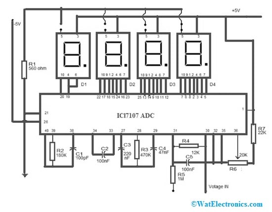
The digital voltmeter circuit with ICl7107 ADC is shown below. This circuit is precise and also a very helpful digital voltmeter that uses the ICL7107 & LED display. This IC is a low power, very high performance & 3.5 digit ADC. This IC contains an internal circuit for the reference voltage source, display drivers, seven segment decoders & a CLK. This IC has below 10mW power dissipation.
The required components to make this digital voltmeter circuit with ICL7107 ADC mainly include; ICL7107 ADC, resistors like R1 = 560 Ohms, R2 = 180K, R= 470K, R4 = 12K, R5 = 1M, R6 = 20K, R7= 22K, seven segment displays – 4 and voltage supply.
Connect the circuit on a PCB & it can be powered from a dual supply of +/_5V. Give the supply to the circuit & short the i/p terminals for calibration. After that, adjust the R6 resistor so that the seven-segment display reads zero volts. This IC is a CMOS device & it is very responsive to fixed electricity. The seven-segment display used in this circuit is a common anode type.

Digital Voltmeter Circuit Diagram with ICl7107 ADC
Working
This digital voltmeter circuit working is extremely simple. By using this ADC IC, the voltage which needs to be measured can be changed into a digital signal after that this can be decoded to the 7-segment format & after that, it can be displayed.
The type of ADC utilized within ICL7107 is a dual slope. The process happening in ADC follows as; for a fixed time period, the voltage is integrated which needs to be measured to get a ramp at the o/p of the integrator. After that to the integrator’s i/p, a reference voltage of reverse polarity is provided & is allowed to ramp until the integrator output becomes zero.
The time duration to achieve zero for the negative slope can be measured in the CLK cycle of IC & it will be proportional to the voltage within the measurement. In other words, the i/p voltage is evaluated with an internal reference voltage & its result is changed in a digital format.
In the above circuit, the R2 resistor & C1 capacitor are mainly used for setting ICs’ internal CLK frequency. Here, the C2 capacitor will neutralize the variations within the internal reference voltage & enhances the display strength. The R4 resistor controls the voltmeter range. The three displays on the rightmost side are connected to display all digits whereas left most side display is connected so it only displays “1” & “-“.
The pin5 in the circuit is connected to only GND for the third display & its location needs to be changed once you adjust the volt meter range by altering R4. If R4 =12K then it provides a 0-200V range & R4=1.2K then it provides 0 to 20V range.
Advantages
The advantages of the ICl7107 ADC display driver include the following.
- The ICL7107 is highly accurate, economical, and versatile.
- These ICs are monolithic.
- This IC displays from 0 to 1999 digital value.
- It consumes significantly less power.
ICl7107 ADC Display Driver Applications
The applications of the ICl7107 ADC display driver include the following.
- ICL7107 ADC IC is used for conversion from analog to digital equal to 31/2 digits
- ICL7107 is mainly designed for connecting the LED display to it directly.
- These ADC ICs are used in digital panel meter-based applications.
- These are used to measure as well as display analog data.
- This ADC IC is used in digital ammeter and digital voltmeter.
- It is utilized in instrument panel display.
- These ICs are used in non-programming module-based applications.
- It is used in Instrument panel displays.
- This IC includes an internal circuit to drive four seven-segment displays for displaying the voltage measured.
Please refer to this link for the ICl7107 ADC display driver IC datasheet.
Thus, this is an overview of the ICl7107 ADC display driver IC, pin configuration, features, specifications, circuit working, and its applications. This IC is used to measure the maximum voltages from -15V to +15V equivalent to the voltage supply. The digital o/p of this IC varies from 0 to 1999 wherever every digit can be displayed over a single seven-segment display. Thus, if you want to measure and display the voltage on a seven-segment display without using MCU or programming, then this ADC IC might be the correct choice. Here is a question for you, what is ADC?